Wednesday, May 31, 2006

checking DRAMHO move

I moved dramho to 100000 using the .cmd file (to external memory)

program compiles but motor does not run

I have tried moving dramho with the HE file but motor does not work

changed back the dramho and the motor works

I now understand the difference between the internal and the external memory maps

create custom files "internal" and "full_memory map"

afm 060531 (uses HE) works with internal memory map (now saved as internal)

need to find out how I can store the data in zone 6

using F2812_EzDSP_RAM_lnk.cmd

this cmd file is meant for use with the ezdsp board.

It has a small DRAMHO and does not work immediately so I will not waste any more time on it

/*
//###########################################################################
//
// FILE: F2812_EzDSP_RAM_lnk.cmd
//
// TITLE: Linker Command File For F2812 eZdsp examples that run out of RAM
// This linker file assumes the user is booting up in Jump to H0 mode
//
//###########################################################################
//
// Ver | dd mmm yyyy | Who | Description of changes
// =====|=============|======|===============================================
// 1.00| 11 Sep 2003 | L.H. | Changes since previous version (v.58 Alpha)
// | | | Added BEGIN section to the start of H0
// | | | Removed .bss, .const and .sysmem
// | | | These are for a small memory model. All examples
// | | | use the large model.
// | | | Added .esysmem section
// | | | Changed ramfuncs section to load and run from RAM
// | | | (previously this was type DSECT)
// | | | Moved peripheral register files to DSP28_Headers_BIOS.cmd
// | | | and DSP28_Headers_nonBIOS.cmd
// | | | Added CSM_RSVD memory section in FLASHA - this region
// | | | should be programmed with all 0x0000 when using the CSM
// -----|-------------|------|-----------------------------------------------
//###########################################################################
*/

/* ======================================================
// For Code Composer Studio V2.2 and later
// ---------------------------------------
// In addition to this memory linker command file,
// add the header linker command file directly to the project.
// The header linker command file is required to link the
// peripheral structures to the proper locations within
// the memory map.
//
// The header linker files are found in base\DSP281x_Headers\cmd
//
// For BIOS applications add: DSP281x_Headers_nonBIOS.cmd
// For nonBIOS applications add: DSP281x_Headers_nonBIOS.cmd
========================================================= */

/* ======================================================
// For Code Composer Studio prior to V2.2
// --------------------------------------
// 1) Use one of the following -l statements to include the
// header linker command file in the project. The header linker
// file is required to link the peripheral structures to the proper
// locations within the memory map */

/* Uncomment this line to include file only for non-BIOS applications */
/* -l DSP281x_Headers_nonBIOS.cmd */

/* Uncomment this line to include file only for BIOS applications */
/* -l DSP281x_Headers_BIOS.cmd */

/* 2) In your project add the path to base\DSP281x_headers\cmd to the
library search path under project->build options, linker tab,
library search path (-i).
/*========================================================= */
_RTDX_interrupt_mask = ~0x4000; /* interrupts masked by RTDX */

MEMORY
{
PAGE 0 :
/* For this example, H0 is split between PAGE 0 and PAGE 1 */
/* BEGIN is used for the "boot to HO" bootloader mode */
/* RESET is loaded with the reset vector only if */
/* the boot is from XINTF Zone 7. Otherwise reset vector */
/* is fetched from boot ROM. See .reset section below */

RAMM0 : origin = 0x000000, length = 0x000400
BEGIN : origin = 0x3F8000, length = 0x000002
PRAMH0 : origin = 0x3F8002, length = 0x000FFE
RESET : origin = 0x3FFFC0, length = 0x000002


PAGE 1 :

/* For this example, H0 is split between PAGE 0 and PAGE 1 */

RAMM1 : origin = 0x000400, length = 0x000400
DRAMH0 : origin = 0x3f9000, length = 0x001000
}


SECTIONS
{
/* Setup for "boot to H0" mode:
The codestart section (found in DSP28_CodeStartBranch.asm)
re-directs execution to the start of user code.
Place this section at the start of H0 */

codestart : > BEGIN, PAGE = 0
ramfuncs : > PRAMH0 PAGE = 0
.text : > PRAMH0, PAGE = 0
.cinit : > PRAMH0, PAGE = 0
.pinit : > PRAMH0, PAGE = 0
.switch : > RAMM0, PAGE = 0
.reset : > RESET, PAGE = 0, TYPE = DSECT /* not used, */
/*/////////////////////////////////////////////////////////*/
/* .rtdx_text : > PRAMH0, PAGE = 0 /* rtdx code */
/*/////////////////////////////////////////////////////////*/

.stack : > RAMM1, PAGE = 1
.ebss : > DRAMH0, PAGE = 1
.econst : > DRAMH0, PAGE = 1
.esysmem : > DRAMH0, PAGE = 1

/* .rtdx_data : > DRAMH0, PAGE = 1 */

}

current reference lookup for encoder

made a file that converts the reference for hall effects to a reference for the encoder

I had difficulty when I tried to run that as there was apparently not enough room in DRAMH0

I increased the size of DRAMH0 in the cmd file in ccs and then rebuilt the project. This time the project built but the motor did not work.

I then tried with an internal memory map for the cmd file in the ezdsp setup in the model.

This time it I get the same error

[Linking...] "C:\ti\c2000\cgtools\bin\cl2000" -@"Custom_MW.lkf"
>> error: can't allocate .ebss (sz: 00003174 page: 1) in DRAMH0 (avail:
00002000)
>> error: errors in input - afm_060530a.out not built

Build Complete,
2 Errors, 0 Warnings, 0 Remarks.


here is the cmd file that i am using

/* This linker command file is generated by the Target for TI C2000(tm). */


MEMORY
{
PAGE 0 :
PRAMH0 : origin = 0x3F8000, length = 0x002000
RESET : origin = 0x3FFFC0, length = 0x000002
BOOTROM : origin = 0x3FF000, length = 0x000fc0
PAGE 1 :
RAMM0 : origin = 0x000000, length = 0x000400
RAMM1 : origin = 0x000400, length = 0x000400
DRAMH0 : origin = 0x008000, length = 0x002000
DEV_EMU : origin = 0x000880, length = 0x000180
PIE_VECT : origin = 0x000D00, length = 0x000100
FLASH_REGS : origin = 0x000A80, length = 0x000060
CSM : origin = 0x000AE0, length = 0x000010
XINTF : origin = 0x000B20, length = 0x000020
CPU_TIMER0 : origin = 0x000C00, length = 0x000008
PIE_CTRL : origin = 0x000CE0, length = 0x000020
ECANA : origin = 0x006000, length = 0x000040
ECANA_LAM : origin = 0x006040, length = 0x000040
ECANA_MOTS : origin = 0x006080, length = 0x000040
ECANA_MOTO : origin = 0x0060C0, length = 0x000040
ECANA_MBOX : origin = 0x006100, length = 0x000100
SYSTEM : origin = 0x007010, length = 0x000020
SPIA : origin = 0x007040, length = 0x000010
SCIA : origin = 0x007050, length = 0x000010
XINTRUPT : origin = 0x007070, length = 0x000010
GPIOMUX : origin = 0x0070C0, length = 0x000020
GPIODAT : origin = 0x0070E0, length = 0x000020
ADC : origin = 0x007100, length = 0x000020
EVA : origin = 0x007400, length = 0x000040
EVB : origin = 0x007500, length = 0x000040
SCIB : origin = 0x007750, length = 0x000010
MCBSPA : origin = 0x007800, length = 0x000040
CSM_PWL : origin = 0x3F7FF8, length = 0x000008
}


SECTIONS
{
codestart : > PRAMH0, PAGE = 0
.text : > PRAMH0, PAGE = 0
.cinit : > PRAMH0, PAGE = 0
ramfuncs : > PRAMH0, PAGE = 0, TYPE = DSECT
.reset : > RESET, PAGE = 0, TYPE = DSECT
IQmath : > PRAMH0 PAGE = 0
IQmathTables : > BOOTROM PAGE = 0, TYPE = NOLOAD
.stack : > RAMM1, PAGE = 1
.bss : > DRAMH0, PAGE = 1
.ebss : > DRAMH0, PAGE = 1
.const : > DRAMH0, PAGE = 1
.econst : > DRAMH0, PAGE = 1
.sysmem : > DRAMH0, PAGE = 1
PieVectTableFile : > PIE_VECT, PAGE = 1
/*** Peripheral Frame 0 Register Structures ***/
DevEmuRegsFile : > DEV_EMU, PAGE = 1
FlashRegsFile : > FLASH_REGS, PAGE = 1
CsmRegsFile : > CSM, PAGE = 1
XintfRegsFile : > XINTF, PAGE = 1
CpuTimer0RegsFile : > CPU_TIMER0, PAGE = 1
PieCtrlRegsFile : > PIE_CTRL, PAGE = 1
/*** Peripheral Frame 1 Register Structures ***/
SysCtrlRegsFile : > SYSTEM, PAGE = 1
SpiaRegsFile : > SPIA, PAGE = 1
SciaRegsFile : > SCIA, PAGE = 1
XIntruptRegsFile : > XINTRUPT, PAGE = 1
GpioMuxRegsFile : > GPIOMUX, PAGE = 1
GpioDataRegsFile : > GPIODAT PAGE = 1
AdcRegsFile : > ADC, PAGE = 1
EvaRegsFile : > EVA, PAGE = 1
EvbRegsFile : > EVB, PAGE = 1
ScibRegsFile : > SCIB, PAGE = 1
McbspaRegsFile : > MCBSPA, PAGE = 1
/*** Peripheral Frame 2 Register Structures ***/
ECanaRegsFile : > ECANA, PAGE = 1
ECanaLAMRegsFile : > ECANA_LAM PAGE = 1
ECanaMboxesFile : > ECANA_MBOX PAGE = 1
ECanaMOTSRegsFile : > ECANA_MOTS PAGE = 1
ECanaMOTORegsFile : > ECANA_MOTO PAGE = 1
/*** Code Security Module Register Structures ***/
CsmPwlFile : > CSM_PWL, PAGE = 1
}


/* [EOF] afm_060530a.cmd */


which now that i look at it is the same memory mapping as the custom one that I was using.


Try the modified one that is based on jess' (afm_060530.cmd)

same error


[Linking...] "C:\ti\c2000\cgtools\bin\cl2000" -@"Custom_MW.lkf"
>> error: can't allocate .ebss (sz: 00003174 page: 1) in DRAMH0 (avail:
00001000)
>> error: errors in input - afm_060530a.out not built

Build Complete,
2 Errors, 0 Warnings, 0 Remarks.


this is what that cmd memory map looks like


/* This linker command file is generated by the Target for TI C2000(tm). */
/* modified by Greg Heins on 11/12/05 to fix problems with "from memory" block */
/* modified by Greg Heins on 26/05/06 to fix problems with rtdx */

/* MODULE RTDX (taken from the RTDX demo) */
_RTDX_interrupt_mask = ~0x0000;

/* reduce the priority of the interrupt mask - see blog for explanation*/
/*_RTDX_interrupt_mask = ~0x0008;*/


MEMORY
{
PAGE 0: /* Program Memory */
ZONE6 : origin = 0x100000, length = 0x008000
OTP : origin = 0x3D7800, length = 0x000800
BEGIN : origin = 0x3F7FF6, length = 0x000002
/* PRAMH0 has been modifed to match Jess' program */
PRAMH0 : origin = 0x3F8002, length = 0x000FFE
ROM : origin = 0x3FF000, length = 0x000FC0
RESET : origin = 0x3FFFC0, length = 0x000002
VECTORS : origin = 0x3FFFC2, length = 0x00003E
PAGE 1 : /* Data Memory */
RAMM0 : origin = 0x000000, length = 0x000400
RAMM1 : origin = 0x000400, length = 0x000400
DEV_EMU : origin = 0x000880, length = 0x000180
PIE_VECT : origin = 0x000D00, length = 0x000100
FLASH_REGS : origin = 0x000A80, length = 0x000060
CSM : origin = 0x000AE0, length = 0x000010
XINTF : origin = 0x000B20, length = 0x000020
CPU_TIMER0 : origin = 0x000C00, length = 0x000008
PIE_CTRL : origin = 0x000CE0, length = 0x000020
ECANA : origin = 0x006000, length = 0x000040
ECANA_LAM : origin = 0x006040, length = 0x000040
ECANA_MOTS : origin = 0x006080, length = 0x000040
ECANA_MOTO : origin = 0x0060C0, length = 0x000040
ECANA_MBOX : origin = 0x006100, length = 0x000100
SYSTEM : origin = 0x007010, length = 0x000020
SPIA : origin = 0x007040, length = 0x000010
SCIA : origin = 0x007050, length = 0x000010
XINTRUPT : origin = 0x007070, length = 0x000010
GPIOMUX : origin = 0x0070C0, length = 0x000020
GPIODAT : origin = 0x0070E0, length = 0x000020
ADC : origin = 0x007100, length = 0x000020
EVA : origin = 0x007400, length = 0x000040
EVB : origin = 0x007500, length = 0x000040
SCIB : origin = 0x007750, length = 0x000010
MCBSPA : origin = 0x007800, length = 0x000040
RAML0 : origin = 0x008000, length = 0x001000
RAML1 : origin = 0x009000, length = 0x001000
ZONE6 : origin = 0x108000, length = 0x008000
CSM_PWL : origin = 0x3F7FF8, length = 0x000008
/* DRAMH0 has been modifed to match Jess' program */
DRAMH0 : origin = 0x3F9000, length = 0x001000
}

/* all referneces to Zone6 have been changed to PRAM and DRAM */

SECTIONS
{
codestart : > BEGIN PAGE = 0
.text : > PRAMH0 PAGE = 0
.cinit : > PRAMH0 PAGE = 0
.pinit : > PRAMH0, PAGE = 0
.reset : > RESET, PAGE = 0, TYPE = DSECT
IQmath : > PRAMH0 PAGE = 0
IQmathTables : > ROM PAGE = 0, TYPE = NOLOAD
.stack : > RAML1 PAGE = 1
.ebss : > DRAMH0 PAGE = 1
.econst : > DRAMH0 PAGE = 1
.esysmem : > DRAMH0 PAGE = 1
PieVectTableFile : > PIE_VECT, PAGE = 1
/*** Peripheral Frame 0 Register Structures ***/
DevEmuRegsFile : > DEV_EMU, PAGE = 1
FlashRegsFile : > FLASH_REGS, PAGE = 1
CsmRegsFile : > CSM, PAGE = 1
XintfRegsFile : > XINTF, PAGE = 1
CpuTimer0RegsFile : > CPU_TIMER0, PAGE = 1
PieCtrlRegsFile : > PIE_CTRL, PAGE = 1
/*** Peripheral Frame 1 Register Structures ***/
SysCtrlRegsFile : > SYSTEM, PAGE = 1
SpiaRegsFile : > SPIA, PAGE = 1
SciaRegsFile : > SCIA, PAGE = 1
XIntruptRegsFile : > XINTRUPT, PAGE = 1
GpioMuxRegsFile : > GPIOMUX, PAGE = 1
GpioDataRegsFile : > GPIODAT PAGE = 1
AdcRegsFile : > ADC, PAGE = 1
EvaRegsFile : > EVA, PAGE = 1
EvbRegsFile : > EVB, PAGE = 1
ScibRegsFile : > SCIB, PAGE = 1
McbspaRegsFile : > MCBSPA, PAGE = 1
/*** Peripheral Frame 2 Register Structures ***/
ECanaRegsFile : > ECANA, PAGE = 1
ECanaLAMRegsFile : > ECANA_LAM PAGE = 1
ECanaMboxesFile : > ECANA_MBOX PAGE = 1
ECanaMOTSRegsFile : > ECANA_MOTS PAGE = 1
ECanaMOTORegsFile : > ECANA_MOTO PAGE = 1
/*** Code Security Module Register Structures ***/
CsmPwlFile : > CSM_PWL, PAGE = 1
}


/* [EOF] from_memory.cmd */


that has an even smaller DRAMHO

Monday, May 29, 2006

current feedback shape

I am logging using rtdx at 1000hz. Here is the log of the reference current:


and the feedback

clutching at straws

Just before this weeks meeting with friso, I thought I should try another attempt with the rtdx interrrupt mask that came out of the ezdsp cmd file

_RTDX_interrupt_mask = ~0x4000; /* interrupts masked by RTDX */

that did not work

neither did putting that line in my other cmd file

2nd go at the dsp- bios tutorials (discrepancies)

Step 2:


8. The MySession Profile window should look similar to the following. The actual line number may be different.

I have a code size of 4 instead of 7


10. In the MySession Profile window, look at the number in the Incl. Total column. (Since this function runs once, the Total, Maximum, and Minimum are the same.)

All my incl. columns are 1 - theirs are 2899. Though they suggest that this could vary a bit, it seems unlikely that the include total is 1

The Incl. Total column shows the number of instruction cycles used from the time the assembly code associated with this line begins executing until it finishes executing.

step 4 - creating a config file

Here I needed to add the file to the project to get the generated files - the tutorial did not specify that.

That needed to be done in the next step


When I tried to rebuild, I have the signal referencing errors that have plagued me previously.

that was because I did not add the hellocfg.cmd file - that may solve a few problems

more problems after I added that file and got rid of the original .cmd file

----------------------------- hello.pjt - Debug -----------------------------
[Linking...] "C:\ti\c2000\cgtools\bin\cl2000" -@"Debug.lkf"
>> error: symbol _c_inhttp://www.blogger.com/moderate-comment.g?blogID=18662253
Moderate comments t00 is defined multiple times: boot.obj
(C:\ti\c2000\cgtools\lib\rts2800.lib) and boot.o28l
(C:/ti/c2000/bios/lib/biosi.a28l)
>> error: errors in input - ./Debug/hello.out not built

Build Complete,
2 Errors, 0 Warnings, 0 Remarks.


I don't understand that one as I think that I have done everthing asked in the tutorial and it worked last time I did the tutiorial.


no time, nic is about to give me a hand, go back to the old tutorial and continue from step 6.

Sunday, May 28, 2006

DSP/BIOS - high priority

I think that I had improved performance from my program when I removed all the excess data type conversions. This indicates that I have performance limitations that would be best addressed if I can analyse the program using dsp/bios tools.

I have searched further to find information about including dsp/bios in a simulink generated project and I found the following about c6000 embedded targets:


www.mathworks.com/access/helpdesk/help/toolbox/tic6000/using_dsp_bios8.html


Code Generation with DSP/BIOS

While generating code that includes the DSP/BIOS options is straightforward using the Incorporate DSP/BIOS option in the TIC6000 code generation options


from that, as I cannot find that option in the board configuration, it would seem that I have to add it in using ccs.

Friday, May 26, 2006

logging current using pid_current_control_rtdx_7

Seeing as I seem to be able to log data at 100Hz, I thought that I should try to log the current.

for some reason, I can only log one "from rtdx" as soon as I enable another channel, the first one is disabled.

I tried logging the feedback current at 500hz and it looked pretty bad.

definetly bed time.

how slow do I need to use RTDX logging

1k is almost okay
500Hz is not much better (almost okay)
100Hz is pretty good - I don't think that I could notice it!!

using the internal memory map with rtdx

I copied the internal memory map fil, added the rtdx interrupt mask and saved it so that it can be used as a custom file.

Now it works with an rtdx block inside at 10k, however if rtdx is enabled and logged at 10k the motors still slows.

getting everything into int32 or sfix32

I ended up getting almost everything into double in pid_current_control_5, however from looking at the examples, I think i really should have everything in int32 or sfix32

having everything in 32 bit ended up using too much memory.

Now everthing is at int16 except for the original "from memory" blocks that read the registers for the current sense and the external memory for the hall effect. The controller also needs sfix(32) so there needs to be a conversion before and after that.

getting rid of data type conversions (5)

having just proved that I got no where with the interrupt mask, I had a look at the generated code and it is pretty long. One thing that I have been meaning to do is to remove all the data type conversions. That shoudld make it a bit more efficient.

start with the HE out block and change input to double

compiles, loads, does not run

I think that I tried that before -

try to change all to int16

compiles, loads, does not work

HE INPUT MUST BE UINT16!!

try to remove the converstions from IA capture where the divide is.

Works!!

in the same block, I changed the gain, the divide and the sum data type to "inherit via back propogation"

compiles. loads, Does not work

tried to change just the sum back to "inherit via internal rule" but that did not work

I have changed them all back to "inherit via interenal rule"

works again - try "same as input"

compiles. loads, Does not work

I assume that i am loosing some data - make it uint32 on the inputs

[Linking...] "C:\ti\c2000\cgtools\bin\cl2000" -@"Custom_MW.lkf"
>> error: can't allocate .text (sz: 00000fff page: 0) in PRAMH0 (avail:
00000ffe)
>> error: errors in input - pid_current_control_rtdx_5.out not built

Build Complete,

must be time to give that caper up.

changed them all back

works again

tried to remove the conversions from Ib and Ic capture

compiles, loads, runs


i have makd a whole lot of stuff double without any explicit conversion blocks

motor runs

made a whole lot more stuff double in Ib and Ic

works

made the output of HE_out double and also the input to rtdx


[Linking...] "C:\ti\c2000\cgtools\bin\cl2000" -@"Custom_MW.lkf"
>> error: can't allocate .text (sz: 000010e5 page: 0) in PRAMH0 (avail:
00000ffe)
>> error: errors in input - pid_current_control_rtdx_5.out not built

Build Complete,
2 Errors, 0 Warnings, 0 Remarks.


I have an issue with the size of the memory map

I have changed them back and will have a go altering the memory map

first step is to remove the rtdx and use the internal memory map

works

now try to change the things back to "double"

compiles - which is better than last time
loads
motor turns!!

made some stuff (including look up tables) in the reference generation block double

motor turns!!

pid_current_control_rtdx_4 - lowering rtdx priority

note that // is not an appropriate version of comment in a cmd file

I tried to change to a mask of 8 but it did not seem to work

I changed back to 0 but it still did not work

shut matlab and ccs down and tried 0 again - okay

Tried 8 again - okay

now try to add i a rtdx block with no rate transiiton (therfore 10k)

works

try an rtdx block that I can talk to

still is affected but logs okay

try using a rate transition so that I am only logging at 1k

compiles

loads

motor runs

motor is affected by rtdx

just to check that the rtdx interrupt mask mattered, I have changed it back to 0

compiles, loads, motor runs, rtdx enable has same effect.

RTDX_interrupt_mask


What is RTDX_interrupt_mask ?
Most RTDX function calls can be made from multiple threads, even inside interrupt handlers.However, the global data structures modified by these functions must be protected so that only one function at a time can modicy them.

For this purpose, the symbol _RTDX_interrupt_mask is defined at link time to identify clients of RTDX and protect RTDX critical sections. _RTDX_interrupt_mask specifies the interrupts to be temporarily disabled inside RTDX critical sections. This also temporarily disables the other clients of RTDX and prevents another RTDX function call.

Only those interrupts that may call an RTDX function need to be masked. With this design, you can carefully select the interrupts to be disabled. Other non-masked interrupts will still occur even inside RTDX critical sections.

For TMS320C54x applications, the mask is applied to the IMR register just befor entering the critical section, disabling only those interrupts specified. Upon exiting the critical section, the IMR is restored to its prior value.

The symbol _RTDX_interrupt_mask must be specified in the linker command file. The interrupts to be masked are indicated by a zero at the appropriate bit position. In the example below, the ones complementer operator (~) is used to define the symbol.


_RTDX_interrupt_mask = ~0x0008;
/* interrupts masked by RTDX */


This definition of _RTDX_interrupt_mask disables the timer interrupt when entering an RTDX critical section

is high speed rtdx supported on c2800?


Problem:
Which processors support high-speed RTDX?


Solution:
High-speed RTDX is supported on the C621x, C671x, & C64x version 1.1 (driver included in C64x CSL) processors with the XDS560. C55x, C54x, C28x and C24x devices can also be used with the XDS560, but only standard speed RTDX is available for these devices.

rtdx bandwith - found on ti faq


Problem:
What bandwidth rates can standard JTAG RTDX achieve?

Solution:
The maximum bandwidth possible for standard JTAG RTDX varies greatly based on several different factors. The primary factors include:
----The RTDX implementation method used for the target processor: this varies from a relatively inefficient polled interface (used in the C54x), to one that is interrupt-driven (used on the C6201). Data rates range between approximately 8 and 11 KB/second for the C54x. In a polling implementation these rates are affected by what the CPU is doing, since maximum rates are only accomplished if the CPU polls the status as soon as the channel becomes available. For the C6000 rates have been achieved of up to 20-50 KB/second.
----The silicon emulation capabilities available on that target processor: this varies from polling mechanisms to DMA to other implementations.

lowering rtdx priority

from the previous help extract, it seems that rtdx calls override all other interrupts. I want to change that to ensure that the critical interrupts are allowed to run.

If your application does not make RTDX calls from SWI or TSK threads, you may modify bits in this mask to enable specific high-priority interrupts. See the RTDX documentation for details.

not really using cdb file

When I rebuild the project with the cdb file in it in ccs, I get an error saying

[Linking...] "C:\ti\c2000\cgtools\bin\cl2000" -@"Custom_MW.lkf"

undefined first referenced
symbol in file
--------- ----------------
SWI_D_rdytab C:\Matlab_data\rtdx_current_control\gregs_hopeful_configcfg.obj
_HWI_STKTOP C:\Matlab_data\rtdx_current_control\gregs_hopeful_configcfg.obj
_KNL_exit C:\Matlab_data\rtdx_current_control\gregs_hopeful_configcfg.obj
TSK_VCREATEFXN C:\Matlab_data\rtdx_current_control\gregs_hopeful_configcfg.obj
_UTL_doError C:\Matlab_data\rtdx_current_control\gregs_hopeful_configcfg.obj
PIP_F_start C:\Matlab_data\rtdx_current_control\gregs_hopeful_configcfg.obj
GBL_boot C:\Matlab_data\rtdx_current_control\gregs_hopeful_configcfg.obj
TSK_VDELETEFXN C:\Matlab_data\rtdx_current_control\gregs_hopeful_configcfg.obj
KNL_glue C:\Matlab_data\rtdx_current_control\gregs_hopeful_configcfg.obj
LNK_D_dataReadyMask C:\Matlab_data\rtdx_current_control\gregs_hopeful_configcfg.obj
_UTL_doAbort C:\Matlab_data\rtdx_current_control\gregs_hopeful_configcfg.obj
IDL_F_loop C:\Matlab_data\rtdx_current_control\gregs_hopeful_configcfg.obj
M0SARAM$B C:\Matlab_data\rtdx_current_control\gregs_hopeful_configcfg.obj
iRTA_F_or C:\Matlab_data\rtdx_current_control\gregs_hopeful_configcfg.obj
_HWI_STKBOTTOM C:\Matlab_data\rtdx_current_control\gregs_hopeful_configcfg.obj
_RTDX_Buffer_Start C:\Matlab_data\rtdx_current_control\gregs_hopeful_configcfg.obj
GBL_stackbeg C:\Matlab_data\rtdx_current_control\gregs_hopeful_configcfg.obj
M0SARAM$L C:\Matlab_data\rtdx_current_control\gregs_hopeful_configcfg.obj
_UTL_doPutc C:\Matlab_data\rtdx_current_control\gregs_hopeful_configcfg.obj
_MEM C:\Matlab_data\rtdx_current_control\gregs_hopeful_configcfg.obj
PRD_F_tick C:\Matlab_data\rtdx_current_control\gregs_hopeful_configcfg.obj
FXN_F_selfLoop C:\Matlab_data\rtdx_current_control\gregs_hopeful_configcfg.obj
GBL_stackend C:\Matlab_data\rtdx_current_control\gregs_hopeful_configcfg.obj
HWI_D_spsave C:\Matlab_data\rtdx_current_control\gregs_hopeful_configcfg.obj
PRD_D_tablen C:\Matlab_data\rtdx_current_control\gregs_hopeful_configcfg.obj
_RTDX_Buffer_End C:\Matlab_data\rtdx_current_control\gregs_hopeful_configcfg.obj
_FXN_F_nop C:\Matlab_data\rtdx_current_control\gregs_hopeful_configcfg.obj
_KNL_run C:\Matlab_data\rtdx_current_control\gregs_hopeful_configcfg.obj
L0SARAM$B C:\Matlab_data\rtdx_current_control\gregs_hopeful_configcfg.obj
LNK_D_fromHostMask C:\Matlab_data\rtdx_current_control\gregs_hopeful_configcfg.obj
CLK_F_isr C:\Matlab_data\rtdx_current_control\gregs_hopeful_configcfg.obj
PIP_D_tabbeg C:\Matlab_data\rtdx_current_control\gregs_hopeful_configcfg.obj
L0SARAM$L C:\Matlab_data\rtdx_current_control\gregs_hopeful_configcfg.obj
_UTL_halt C:\Matlab_data\rtdx_current_control\gregs_hopeful_configcfg.obj
_MEM_init C:\Matlab_data\rtdx_current_control\gregs_hopeful_configcfg.obj
RTA_F_dispatch C:\Matlab_data\rtdx_current_control\gregs_hopeful_configcfg.obj
RTDX_F_isr C:\Matlab_data\rtdx_current_control\gregs_hopeful_configcfg.obj
_TSK_startup C:\Matlab_data\rtdx_current_control\gregs_hopeful_configcfg.obj
_TSK_setup C:\Matlab_data\rtdx_current_control\gregs_hopeful_configcfg.obj
_KNL_queues C:\Matlab_data\rtdx_current_control\gregs_hopeful_configcfg.obj
LNK_F_dataPump C:\Matlab_data\rtdx_current_control\gregs_hopeful_configcfg.obj
TSK_VEXITFXN C:\Matlab_data\rtdx_current_control\gregs_hopeful_configcfg.obj
GBL_F_version C:\Matlab_data\rtdx_current_control\gregs_hopeful_configcfg.obj
_TSK_init C:\Matlab_data\rtdx_current_control\gregs_hopeful_configcfg.obj
PIP_D_tablen C:\Matlab_data\rtdx_current_control\gregs_hopeful_configcfg.obj
_TSK_exit C:\Matlab_data\rtdx_current_control\gregs_hopeful_configcfg.obj
SWI_F_enable C:\Matlab_data\rtdx_current_control\gregs_hopeful_configcfg.obj
IDL_F_busy C:\Matlab_data\rtdx_current_control\gregs_hopeful_configcfg.obj
IDL_F_init C:\Matlab_data\rtdx_current_control\gregs_hopeful_configcfg.obj
>> error: symbol referencing errors - 'pid_current_control_rtdx_3.out' not
built


I dont really think that the DSP/BIOS bit is working. I am not actually sure if it is worth pursuing as the RTDX tutorials from simulink do not use dsp/bios setup.

I think that I need to pursue the rtdx interrupt mask to ensure that high priority interrupts (ie current sensor info) override the rtdx calls.

RTDX manager properties - help extract

The following target configuration properties can be set for the RTDX module in the RTDX Manager Properties dialog of the Configuration Tool or in a DSP/BIOS TextConf script:

Enable Real-Time Data Exchange (RTDX). This box should be checked if you want to link RTDX support into your application.

TextConf Name: ENABLERTDX Type: Bool

Example: RTDX.ENABLERTDX = true;

RTDX Mode. Select the port configuration mode RTDX should use to establish communication between the host and target. The default is JTAG for most targets. Set this to simulator if you use a simulator. The HS-RTDX emulation technology is also available. If this property is set incorrectly, a message says "RTDX target application does not match emulation protocol" when you load the program.

TextConf Name: MODE Type: EnumString

Options: "JTAG", "HSRTDX", "Simulator"

Example: RTDX.MODE = "JTAG";

RTDX Data Segment (.rtdx_data). The memory segment used for buffering target-to-host data transfers. The RTDX message buffer and state variables are placed in this segment.

TextConf Name: RTDXDATASEG Type: Reference

Example: RTDX.RTDXDATASEG = prog.get("myMEM");

RTDX Buffer Size (MADUs). The size of the RTDX target-to-host message buffer, in minimum addressable data units (MADUs). The default size is 1032 to accommodate a 1024-byte block and two control words. HST channels using RTDX are limited by this value.

TextConf Name: BUFSIZE Type: Int16

Example: RTDX.BUFSIZE = 258;

RTDX Interrupt Mask. This mask interrupts to be temporarily disabled inside critical RTDX sections. The default value of zero (0) disables all interrupts within critical RTDX sections. Such sections are short (usually <100 cycles). Disabling interrupts also temporarily disables other RTDX clients and prevents other RTDX function calls.

You should allow all interrupts to be disabled inside critical RTDX sections if your application makes any RTDX calls from SWI or TSK threads. If your application does not make RTDX calls from SWI or TSK threads, you may modify bits in this mask to enable specific high-priority interrupts. See the RTDX documentation for details.

TextConf Name: INTERRUPTMASK Type: Int16

Example: RTDX.INTERRUPTMASK = 0x00000000;

See Also

RTDX Object Properties

RTDX topics

Manager properties

trying to get a dsp/bios version of my current controller working

If I can get the cdb file working, i can add i to the program using add

add
Add files to the active project in CCS or add a new typedef

Syntax
add(cc,'filename')
info = add(cc.type,'typedefname','datatype')


I tried adding code similar to that tot the initialisation for the current block and it said that there was an error as it already was in the project.

I checked and sure enough, it was there and the program is working with it in. I guess that to get it in there, I have to add it from ccs once and then it stays in there.

Unfortunatly, for some reason, when I try to see the cpu execution graph, I still get an error saying that this is not a DSP/BIOS program.

Thursday, May 25, 2006

summary before lunch

Here is where I am at:

1. I can add rtdx blocks to my models if I add:

/* MODULE RTDX (taken from the RTDX demo) */
_RTDX_interrupt_mask = ~0x0000;


to my cmd file.


2. Now that I do not have any to memory or from memory blocks, i can use the standard cmd file with the memory map set to internal. However as this cmd file does not reference the _RTDX_interrupt_mask, I cannot use rtdx blocks


3. When I use RTDX blocks with the open loop program, it runs okay as regardless of the sample time as long as the rtdx blocks are disabled.


4. When I use RTDX blocks in the open loop program, the motor's operation is effected when i enable the rtdx if the rtdx sample time is above about 0.0002 (5k).

5. When I use RTDX blocks in the closed loop program, the motor's operation is effected if I have a diabled rtdx block with a sampling rate that is too fast

6. in the closed loop program the motors operation is further effected if I try to enable the rtdx block

7. This seems unresonable that the operation of the DSP should be effected. I cannot look at the cpu loading unless I figure out how to set the program up as a DSP/BIOS program

i had an idea in the shower

maybe now that I am not using any of the "to memory" or "from memory" blocks other than those that reference the registers, I can use the standard memory map. Then i can use a .cdb file and have a look at the cpu loading and stuff.


pid_current_control_rtdx_3.mdl

check that it works without rtdx

works

remove the config block and replace with default

needed to change the name to: F2812 eZdsp

got the following error message when ccs tried to load the .out file

Data verification failed at address 0x100000
Please verify target memory and memory map


then

Data verification failed at address 0x1081C0
Please verify target memory and memory map


then

1081c2

1080e2

than three others

try to set up using internal memory map

SEEMS TO WORK - NOW I CAN TRY TO USE A CDB FILE

adding a .cdb file gives me 1 error

I tried to run with an rtdx block but no reference to rtdx in the cmd file.

motor squeeled and drew heaps of current then stopped working. Thankfully it still works when I remove the rtdx block and rebuild

pid_current_control_rtdx_2 - only 1 lot of transitions

I am hoping that my problem may come from having too many tranistions in my system

I have saved the program to pid_current_control_rtdx_2 and will first try to run the control loop at 5k to see if that is okay for logging.

I still have the ts_current_sense at 10k

the motor is a bit jerky, however only draws about 2.5A

when RTDX is enabled, it still makes a noticible difference.

just before I go to bed, I will get rid of all the atomic subsystems that I was going to use to diable and enale interrupts


matlab compiles

ccs links and loads

motor turns - maybe a bit more smoothly

try to enable RTDX

motor completely stops while logging is taking place


I tried in vain to add an bios cdb file so that I could see cpu usage but it just stufffed it all up


[Linking...] "C:\ti\c2000\cgtools\bin\cl2000" -@"Custom_MW.lkf"
>> error: symbol _RTDX_Buffer is defined multiple times:
C:\Matlab_data\rtdx\c2812rtdxtest_7_c2000_rtw\gregs_hopeful_configcfg.obj and rtdx_buf.obj (C:/ti/c2000/rtdx/lib/rtdxx.lib)

>> error: errors in input - pid_current_control_rtdx_2.out not built

Build Complete,
2 Errors, 0 Warnings, 0 Remarks.


definetly bed time

Wednesday, May 24, 2006

more current control with rtdx

I have slowed the sampling rate for current control down to 0.01 and the motor still freezes.

Try sample_time_rtdx = 1

no better - try getting rid of the rtdx block - maybe the data tpe or the rate transition that is the problem

moves a bit but still pretty much frozen - try to remove the data type conversion

running fine now - data type conversion seems to be the problem

I would try without a conversion but I am not sure if i can safely make the HE int16. I will try to do that without any rate transition or rtdx block

That works - now I can try a rate transition and a rtdx block back in

matlab compiles

ccs links and loads

motor runs really jerky

in desparation, I have slowed SAMPLE_TIME down to 0.0001. I cannot remember what that did to the controller.

Does not work - try also reducing the ts_current_sense to 0.0001

that sort of works (jerky and draws 10A instead of 2A when working well and 15A+ when really bad.

I will try that setup without the rtdx at all and see if it works better.

back to smooth and 2A

Just add the rate transition

back to the old problems (10A) I have had these problems before with rate transitions but I was not sure how I got rid of them

It may be worthwhile removing the "deterministic daterministic data transfer" box

still jerky

now I have just put in the to RTDX without any rate transition

yay - worked

Now time to try to log the data. From past experience, this is where I will run into trouble as the high RTDX logging speed will trip up the processor

it slowed down the processor

70 per second = 70/8 mechanical hz = 525 rpm?

current control with rtdx

check that afm14 works (PID control)

works

save afm14 to rtdx_current_control directory

trying int16 again now that I have the slower sample time

seems to be fine at a lower sample time.

that is good as now I can look at the current controller

faster RTDX time while enabled

now that I have learnt that the problem with RTDX comes when it is enabled, I know that I should only be enabling for a short time.

There is a noticible effect on the motor when I log at 10k, but not when I log at 1k. How about 5k? sample_time_rtdx = 0.0002.

Seems to log okay with no noticible interruption of the motor but the hall effect plot is pretty crappy still.

another guess at speed would be 7 HE cycles in 0.1 sec = 70 HE cycles in 1 sec = 70/8 hz = 8.75 = 8.75*60 rpm = 525rpm

Tuesday, May 23, 2006

motor speed check

8 hall effect cycle in 0.2 sec

which is 1 mech rev / 0.2 sec

or 5rps

300 rpm

but it is actually at 179rpm

strange

trying to figure out when in the data logging, the motor gets hung up

the motor definetly gets hung up when RTDX is enabled. I have made sure that while the data is being transferred to the PC, the RTDX is no longer enabled.

Maybe it woudl be better if I used the wait function rather than continually polling the num_messages.


% WAIT
% Check the number of available messages to read from the target.
num_of_HE_data = cc.rtdx.msgcount('ochan_HE');
while num_of_HE_data <= TotalSamples
num_of_HE_data = cc.rtdx.msgcount('ochan_HE');
end

changed to

WaitTime = LogTime*1.1;
wait(WaitTime);

that function sucks - could not be bothered

try to log at 1k

i have a feeling that the motor is not going as fast as it should - better check how long a rev takes with the data that comes out.

That is fine - time to try to get it going with the current controlled stuff

nicer file for logging data

at the moment it is a bit clumsy having three files to use.

I think that I should have one that will do all the logging.

Here is the plan

define the sampling rate

check if there are any channels open and flush them if nessesary

enable the channels

wait 2 sec

read in 1 sec data

close all the rtdx stuff


I have done all this but the reading in really stuffs up the motor. Maybe I cannot sample that fast.

There is some pretty corrupted data in that file:

16256
1
4
16512
4
4
4
4
4
16512
16512
4
16512
16576
6
16576
6
16576
6
6
6
6
6
6
6
16576
16576
6
16448
16448
3
16448
3
3
3


I will try to have a large buffer so that I only need to read in after logging is complete.

still corrupted

turn off echo to speed stuff up.

here is a list of the strange numbers and their relationship to

16512 16384 128
16512 16576 -64
16512 16512 0
16512 16448 64
16512 16544 -32

0 1
1 2
2 4
3 8
4 16
5 32
6 64
7 128
8 256
9 512
10 1024
11 2048
12 4096
13 8192
14 16384
15 32768


from this table, it seems like it has something to do with unsigned int/ signed int

i have tried changing to uint16 but it does not like

I have tried changing to uint8 in both the m file and the mdl file.

for some reason that fixed things up

how fast can I read in??

at the moment, I am only reading in at 0.1 seconds - try 0.01

works - try 0.001

works - try 0.0001

works - this is wacky!!!

that is fast enough for me. I will come back to this later if I need.

reading rtdx

now that I have a model working with an rtdx block inside, it is time to attempt to read the data.

I have created rtdx initialise, finalise and communication.

I think that this is the plan:

run initialise
run communitation where the first thing that is done is stop the acquisition

I attempted to use a while loop to read in the data:

% read in the data
i = 0;
while num_of_HE_data ~= 0
i=i+1;
HE_vector = cc.rtdx.readmsg('ochan_HE','int16',[2 1],1);
HE_data(i) = HE_vector(2);
num_of_HE_data = cc.rtdx.msgcount('ochan_HE');
end

but for some reason:

HE_vector = cc.rtdx.readmsg('ochan_HE','int16',[2 1],1);

was printed everytime

it also did that for the if version

num_of_HE_data = cc.rtdx.msgcount('ochan_HE');

for i = 1: num_of_HE_data
HE_vector = cc.rtdx.readmsg('ochan_HE','int16',[2 1],1);
HE_data(i,1) = HE_vector(2);
end

I think that the while version is a little more robust in that it can cope with new data but now that I think about it, it is probably better if that does not happen as that would possibly allow data in the wrong order.

USE THE IF VERSION

I am a bit concerned that there is always 12545 messages

originally there was a slowly increasing number of meassages

maybe I should check if there are always the same messages

initialse'
communicate
finalise
initialise
communicate and chnage the variable
finalise

why 12545?

I thought that that may be to do with the buffer that I created but I left that out of the initialisation code. I should put that back later.

Each lot of data is exactly the same: flush does not seem to be working. I will try stopping the processor.

stopping the processor does not work. Try rebuilding the mdl

does not seem to work - num of msgs is 12545 immediately

but the data is different

I need a quicker way of clearing all that data - why is flush not working?

I have tried resetting the cpu.

now there are always no messages???

I added the buffers incase that was an issue - not

I discoverd that in the initialisation file, I was not:

% enable the RTDX interface
cc.rtdx.enable;

now it is working again. I still have to figure out how to clear the old data without resetting the cpu.

Now it seems that I am getting new data. I assume that what was happening before was that I was not reading in any new data as I was not enabling the interface.

Monday, May 22, 2006

more rtdx fun

I need to figure out how to get this all going without freezing. ver4 is still just giving a high pitched whine.

m file version 2 (note that you need to also copy the fig file of the same name)
mdl version 6

I have removed the referenece to the input rtdx blocks and have only got the output block in the m file. I have also removed the input blocks from the simulink model and only have a constant going into it.

that does not work from the m file

it also does not work with the motor

I have tried attaching the rtdx block to the model on the assupmtion that it could not deal with multiple threads but the motor did not work then either.

I have now tried removing the rtdx block all together to see if the motor works

motor does not work which is a relief.

there is a warning that some block in the PWM out are not connected. Matlab has frozen so hopefully those blocks that were not connected were causing the problems.

those that were not connected were the "from memory" blocks that are meant to be disconnected - bugger

motor still does not work

start 7.mdl using 6-wire-simple

motor works - now add rtdx block for the HE from library browser

compiles

even loads into dsp

but motor does not run

tried slowing down the sampling rate on the rtdx to 0.1 sec

motor runs finally.

now I should be able to set up a channel and read in the data.

must be lunchtime

more getting rtdx to work

c2812rtdxtest_3.mdl - working without the additional block with just running the matlab script manually and building the code as per normal.

I also am using SAMPLE_TIME.


c2812rtdxtest_4.mdl add 6 wire openloop to the model.

the plotting works but not the motor.

try to have a different sampling time for RTDX - 0.1SEC

EXCELLENT working...

now I need to see if I can get this stuff logging real data.

first step will be to see if I can change the duty cycle manually.


I have strated having problems after I shut down the gui window while the motor was runnig. This froze the motor and I have been unable to get teh motor to run again.

it works on 6-wire-simple but just a high frequency scream when I go back to the other program - must have jsut been a fluke before - try sample time = 1 sec

still does not work - must be lunch time.

Sunday, May 21, 2006

Modifying the rtdx demo

1. note that there is no cdb file connected with this project

2. I cannot understand how the "build/Reload and Run" block runs anything

3. there is a warning that comes up in ccs when I run the program that it is not a BIOS/somethinge else program. I have had this warning before.

4. the only additional line that has been added to their cmd file is:
_RTDX_interrupt_mask = ~0x0000;


Other than the "this is not a bios program" error, this all seems to be working pretty well. I will slowly change this program until it resembles a motor control program, in the following order

1. change the configuration to use my custom cmd file so that the memory map works (or change mine so that it uses the standard memory map)

2. Add in a motor controller

3. Connect the RTDX blocks to the error.

4. Attempt to modify the plotting file.

RESULTS

c2812rtdxtest_2
1 - my program works with the RTDX line added to the custom cmd file. The demo then works using my custom cmd file.

c2812rtdxtest_3
2. added stuff from AFM14 (pid)

SAMPLE_TIME not defined

not a bios problem error came up twice

Plot does not display properly

motor does not turn properly

rebuilt afm 14 to check that motor turns using that one

only one bios error message - motor turns fine

thinking that it may be the monitoring that was slowing everything down, I tried running the progrem just from ccs but still had the same problem.


c2812rtdxtest_4

I will try checking the sample times in the RTDX stuff to SAMPLE_TIME

motor and plot still not working

Webinar on C2000 embedded code generation

note that you can force a system to be both an atomic subsystem and also reusable.

Insert block descriptions in code

html code generation report

model assistant tool

check the "demos" for RTDX

are there tutorials for embedded target?

Friday, May 19, 2006

back to the evil RTDX tutorial

trying to increase the load as suggested and even at maximum load (131071) I only have about 55% of CPU load. This is much more than the 1500 that they suggest.

I think that it is about bed time.

Thursday, May 18, 2006

web search

Despite my best intentions, I lost motivation to do the tutorials as they were not working and I decided to check on what the formums have to say.

As usual, they are a pretty thin on solutions, however here are some possible leads:


Does anyone know if there will eventually be a CSL for the 2812? I
have begun to incorporate BIOS in my programs and it seems to be much
easier to work with peripherals if there was a CSL like the 6713 or
any of the other "supported" processors. If there is not a proposed
CSL, is there documentation on how to create one?

-Mark


1- Consider using the s-function builder in simulink to insert your RTDX
calls.
2- For defining RTDX channels at the top of your source file, you can use
the custom code blocks.
3- You would still need to add the rtdxx.lib library to the project before
buildling it though, but this should be an easy step.

Good luck!
Mazen

Trying to get inspired and actually get somewhere with RTDX

It must be at least 2 weeks now that I have been bogged down with this RTDX trouble. If I do not get things happening soon, the end of june deadlines will start to be difficult.

I think that I have to be pretty hard headed and work my way through all the tutorial rather than trying to use a little bit of info in the hope that it will be a shortcut.

I will try to only discuss what I learn from the RTDX debugging tutorial here.

Here is a listing of the files that I am using, the tutorial explanation of them and my interpretation of that:

volume.cdb. This is the configuration file for the project.

I think that this will be the main file that I need to get correct. It has the potential to get the memory mapping set up as well. When it is saved, it creates many other files where I think that my problem lies.

volumecfg.cmd. This linker command file is created when you save the configuration file.

I really don't understand much abou this.

volumecfg.h. This header file is created when you save the configuration file. It includes DSP/BIOS module header files and declares external variables for objects created in the configuration file.

nor this

volumecfg.s28. This assembly file is created when you save the configuration file and contains DSP/BIOS configuration settings.

volumecfg.h28. This header file is created when you save the configuration file and is included by volumecfg.s28.

volumecfg_c.c. This file is created when you save the configuration file. It contains code for Chip Support Library (CSL) structures and settings.

Hopefully I can come back and explain what each of these does a bit better in the future


On page 4, I am back to the problem that I had when I gave up before. They have an excectution graph that has exactly 10 KNL_swi for each processing_SWI.


mine, however is not nearly as nice with the processing_SWI going off all over the place:


I think that hopefully this problem will not affect what I am trying to do. I will continue but keep in mind that this may be the cause of future problems.

I had another thought that this problem may be caused by the ezdsp being connected to the motor interface board. I disconnected it and got the following fom the execution graph:


that is a little more like what I should get.


I should ask Nic what on the board could be affecting it in that way.


I now have a problem that the execution graph is not updating. It sort of works if I start and stop the CPU, however it used to update automatically.

I got the automatic update happening by reopening ccs and reloading the project. However the execution graph still has problems:

in this example, there are too many processing_SWI calls:


in this example, there are too few processing_SWI calls:


I tried "syncronise sliders" in the property page part of the RTA control panel. That did not seem to help.

Sunday, May 14, 2006

afm15 - more on RTDX

Just discovered if you modify the .cmd file in ccs, then next time you compile from matlab, it does not overwrite the changes. Normally the command file is created as a copy of:

file: F2812simulink.cmd

path: C:\Program Files\MATLAB71\toolbox\ccslink\ccslink

I have previously modifed this file so that the memory mapping matched that in jess' cmd file.

To get the RTDX file working, i have needed to add:

/* MODULE RTDX */
_RTDX_interrupt_mask = 0x0;

this is the rtdx setup line from the rtdx tutorial example.

This allows the program to be built, however when I try to use dsp/bios > message log, the following message appears:

Message Log:
Load DSP/BIOS program to use control.

When I try to run the program, the following message appears:

not a BIOS/something else program

Strange thing is that this message only came up the first two times I tried to run the program and after that it would allow me to run the program.


I think that it would be a better way to do this by creating a cbd file that would define the rdtx and also the memory map. When i try to do this, and replace the .cmd file with the one that teh .cbd file creates, i get the following error messages:

>> error: symbol _RTDX_Buffer is defined multiple times:
C:\Matlab_data\May06\afm15_c2000_rtw\afm15cfg.obj and rtdx_buf.obj
(C:/ti/c2000/rtdx/lib/rtdxx.lib)
>> error: symbol _c_int00 is defined multiple times: boot.obj
(C:/ti/c2000/cgtools/lib/rts2800_ml.lib) and boot.o28l
(C:/ti/c2000/bios/lib/biosi.a28l)
>> error: errors in input - afm15.out not built


I am just repeatig the example from the tutiorial and am interested it the

c:\ti\c2800\cgtools\lib\rts.lib. file

I do not have this in my afm15 project. I had better have a look at it incase i have to include it.

You cannot really read this file in a txt editor. now that I look at the previous error messages, there must already be a link to this file as it is referenced in the error message.

just redoing the tutorial, it seems that I do not have to have the rts.lib file:

Right-click on the rts.lib library file and remove it from the project. This library is automatically included by the hellocfg.cmd file

Monday, May 08, 2006

afm 15 - RTDX

must get intermediate info out of the controller if I am to get any further. That should be done using RTDX blocks.

Thursday, May 04, 2006

controller overview


afm14 - sine wave current

as I am a bit stuck at the moment with the controller side of the project, it is time to have a go at a sinusoidal reference.

I really need to create a series of lookup tables that have the reference points with respect to gray code.

here is the m file:

clear

% set up first column as binary encoder
E_binary = transpose(0:1:4095);
Ia_binary(:,1) = E_binary;
Ib_binary(:,1) = E_binary;
Ic_binary(:,1) = E_binary;

% mechanical offset
Mech_offset = 500;

% phase offsets
Ia_offset = Mech_offset + 0;
Ib_offset = Mech_offset + 512/3;
Ic_offset = Mech_offset - 512/3;

Ia_binary(:,2) = sin((E_binary+Ia_offset)/512*2*pi);
Ib_binary(:,2) = sin((E_binary+Ib_offset)/512*2*pi);
Ic_binary(:,2) = sin((E_binary+Ic_offset)/512*2*pi);


%open the lookup table file
load b_to_g.mat;

%use lookup table function
for i = 1:4096
% use lookup to change to gray
Ia(i,1) = interp1(binary_to_gray(:,1),binary_to_gray(:,2),Ia_binary(i,1));
Ib(i,1) = interp1(binary_to_gray(:,1),binary_to_gray(:,2),Ib_binary(i,1));
Ic(i,1) = interp1(binary_to_gray(:,1),binary_to_gray(:,2),Ic_binary(i,1));

end

% copy 2nd column
Ia(:,2) = Ia_binary(:,2);
Ib(:,2) = Ib_binary(:,2);
Ic(:,2) = Ic_binary(:,2);

figure(1)
plot(Ia_binary(:,1),Ia_binary(:,2),Ib_binary(:,1),Ib_binary(:,2),Ic_binary(:,1),Ic_binary(:,2))

figure(2)
subplot(3,1,1)
plotmatrix(Ia(:,1),Ia(:,2))
subplot(3,1,2)
plotmatrix(Ib(:,1),Ib(:,2))
subplot(3,1,3)
plotmatrix(Ic(:,1),Ic(:,2))
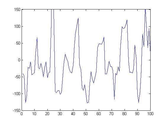


here is the output:


i will use the transition from HE5 to HE1 as a reference. With the current setup, this is at 134.

from the plot in my previous post:


the increasing zero crossing for A will be 512/12 counts after the HE5 to HE1 reference.

the increasing zero crossing for B will be 512*5/15 counts after the HE5 to HE1 reference.

the increasing zero crossing for c will be 512*9/15 counts after the HE5 to HE1 reference.

Wednesday, May 03, 2006

positive and negative shapes

I noticed during the previous trials that the negative shapes were always worse than the positive.

If I put the current sensor facing in the correct orientation, it is actually the high side that is the messy one.

back to pid

seems like I am going around in circles. As I cannot get a good result with hysteresis, I will try again with PID. Here is the image with kp = 0.1 and ki = 1. Current is averaged over 20 samples at a sample time of 1e-5. Main sample time is 4e-5 to correspond with a PWM period of 3000.


this is much weaker than when originally tuning the PID controller. I should be able to repeat the old result by reducing the averaging to 1.

DISREGARD THE PREVIOUS IMAGE. I HAD IT CONNECTED IN A THREE WIRE CONFIG RATHER THAN A 6 WIRE CONFIG.

here is the image with no averaging:


and with averaging of 20.


with a load on:


I THINK THAT I SHOULD BE USING A LOAD FOR ALL MY MEASUREMENTS.


try to remove the ki and use kp = 0.1

dnw

kp = 1

dnw

kp = 10


kp = 5


kp = 3

kp = 1.5

dnw

guess that kp is around add ki = 1


with kp = 1 and ki = 1:


this is really ugly and draws lots of current.

kp = 0.1 and ki = 1 seems pretty good still - work towards that

kp = .5 ki = 1


maybe it is oscillating due to the ki - try:
kp = 0.5 ki = .5


getting worse keep ki at 1 and lower kp to 0.25


a bit better but now I remember that kp = 0.1 and ki = 1 was oscillatory so I should be going for less than that

try kp = 0.1 and ki = 0.5


looks okay try to add kd = 1


does not look much different - try kd = 10


does not look much better and has induced some noise... remove Kd

maybe try to reduce the average width to 10


looks a bit better - try to go to average width of 4 (equate with one pwm width)


looks worse - 10 looks like a good number but I would really like to have it over an integer number of PWM cycles - try 8


okay - try 12


okay but still oscillatory - need to reduce ki and kp

try kp = 0.05 ki = 0.5


a bit slow - try kp = 0.1, ki = 0.3


still a bit slow - 0.1 and 0.5 seems to be the best that I can do for the moment

I may need to add som integral saturatino control

try kic = 1


gone more oscillatory try kic = 0.5

current sensor callibration

after the blown up 2175, I guess that I should check the offset.

Using the simulink program I_cal and looking at the results in the watch window of ccs, I adjusted all of the offsets to 60.

hysteresis control tuning

check that afm12 works

WORKS

move the current sensor with the averaging from afm11. I forgot that this would mean that I would have different sampling rates (main 4e-5 current 1e-5). BUT IT STILL WORKS!!!.. SORT OF


It is really time to figure out what my sample times are doing:

sample time for current sense is 100k (averaged over 20 samples)
sample time for control loop is 25K
PWM period is 3000 (25K)

try a band of 5


Still looks crap - maybe I need to change the average width?

try width of 5


try width of 20 and band of 40


try changing the main sample time to 1e-5

doesnt seem to be much change

pid controller tuning

I am happy with a average width of 20 for the time being. I tried to increase the proportional gain from 0.1 to 1. That gave a worse shape and drew heaps of current (plot below wiht 20A/ division)


I should try to go back to the hysteresis controller.

best average width

now that I have a working controller again, I need to determine the best running average width. Here is the output for a width of 5:


moving average width of 20:

Tuesday, May 02, 2006

busted controller

I think that I stuffed the controller up when I connected it to about 36V by mistake.

discoverd I blew the track to the ground leg of the 5V reg which was connected to the ground leg of the 15V reg. That meant that i had no ground ref for either of the regulators which was why I had 19V on the 5V rail.

once regs were fixed, I needed to change all the gate drivers.

working_masked_openloop is working

could not get afm10 working. the problems turned out to be a software crash - required restart of matlab and ccs.

try afm11 (may) to check if current sensors (replaced) and buffer (replaced) are working.

working

afm11 - multirate problems

with both global and local (I sense) rates at 4e-5, the motor turns.

With the local rate at 2e-5 the motor does not turn.

with both global and local (I sense) rates at 2e-5, the motor turns.

so the problem is not with the magnitude of the sample time, rather with the rate transition.

I need to determine what the smallest possible sample time is.

try 1e-6

motor does not turn

try 1e-5

WORKS

try 5e-6

sort of works

stay at 1e-5 for the moment.


note that this has been at a PWM period of 3000

that corresponds to a PWM rate of 75000000/3000 = 25k

time to average the current over about 5 PWM cycles = 20samples

tried to add a weighted moving average with the default weight of:[0.1:0.1:1 0.9:-0.1:0.1]

DNW

tried an average of 5


seems to be better

tried an average of 10


seems to be not much different - I should have used a multiple of PWM cyles - I will try 20

to make the change of averages easier, I set it up with some inititalisation code

I had problems with 20 and then even 10 so after checking that the program still worked on AFM10 in the april folder. I still have problems.

Maybe try back at 5

still not working properly

try afm11 from april - maybe something is wrong with one of the current sensors and my problem is nothing to do with the moving average.

the problem is still there.

If i think about it, the problem began while I was testing the 10 average. I thought at the time that it was just a glitch but I have not had the motor turning successfully since using closed loop control (only open loop with afm 10)

Check the output of the current sensors under open loop control.

now nothing is even working under open loop control

tried "working_masked_openlooop" and it is not working

THIS IS NOT WHAT I NEED TODAY

start of may - review

after a bit of a break, I need to figure out where I am and what the priorities are.

From reading my previous posts, it would seem that the priorities are:

1. Stick to hysteresis control

2. speed up the current sampling loop (need a multirate system) and average the current

3. figure out why my PWM looks so bad