high current draw on "6 wire simple"
I had problems getting the motor to turn at all using the dsp
Some of the problem lay in that the gate drivers were buggered.
The motor now turns under "working masked open loop"
with "six wire simple" however the power supply is current limiting
I have checked in ccs and the A_effort, B_effort and C_effort are all being generated correctly for the different hall effect states.
now I should check that the gate drivers are getting appropriate signals for each hall effect state.
for HE 6
1-
2+
3-
4-
5-
6+
which translates to A open, B+ and C-
which is correct for HE6
Just out of curiosity, I checked it running on two phases and found that the motor still ran and still drew a lot of current on any combination of phases.
The motor also runs on just one phase B but still seems to draw the same amount of current.
The motor will not run on only phase A and draws no current.
The motor will run on phase C and draws a the same amount of current
If my assumptions are corrent, when the motor is running on all three phases, it will not matter if I remove phase A from the sockets - which it doesnt
there is definetly something wrong with phase A. The gate drive signals seem fine and even the voltage at the phase seems fine.
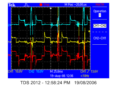
Here is an image of the differential voltage across phase A

and phase B (bit more bus voltage)

to check if it was the motor I measured the resistance across one winding and between phases. It was about 0.04R for each phase and Mohm between phases.
To further check if the problem lay in the motor, I switched the signals around in simulink and switched the bannana plugs around on the board. The problem lay with the PCB and not the motor.
Just incase there was some problem between where on the phase I had clipped on the probes, I put in some short bannana leads and clipped the probes onto them. I still got a reasonable voltage plot.

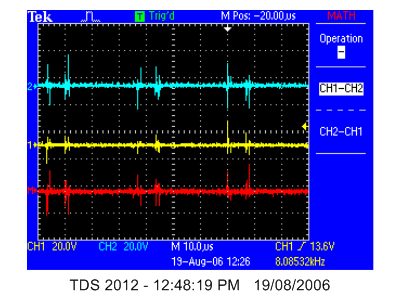
Having a look at much smaller time interval (PWM frequency), Here are the plots for phase B
4 and 6 - high

2 and 5 - open

1 and 3 - low

which is all correct for the switching table (as posted earlier)
HE table
now I will check phase A
2 and 3 - high

1 and 6 - open

4 and 5 - low

just for completeness, I had better check phase C
1 and 5 - high

3 and 4 - open
2 and 6 - low

It seems that the problem with phase A was that the connection with between the board and the banana socket was a not soldered well. Resoldering it seemed to fix the problem of A not working (however it is still drawing heaps of current)
Here is the voltage across A while only running on one phase:

Here is the voltage across B while only running on one phase:

Here is the voltage across C while only running on one phase:
while running like this, I heard a click and afterwards the speed dropped considerably and the current draw remained the same. I will have to find out what I just blew up.
posted by Greg @ 6:35 PM
0 comments
![]()

0 Comments:
Post a Comment
<< Home