Tuesday, March 28, 2006

custom functions

Try:

Calling User-Written C Code Functions

that will not work as it is stateflow stuff for which we do not have the licence.

also note that:

C-code S-functions are supported by Real-Time Workshop. However, M-code S-functions are not supported.

this is what I need to be looking at:

Writing S-Functions for Real-Time Workshop

I want a noninlined function:

NOTE:

Noninlined S-Function Parameter Type Limitations


Parameters to S-functions can be of the following types only:

Double precision

Characters in scalars, vectors, or 2-D matrices

For more flexibility in the type of parameters you can supply to S-functions or the operations in the S-function, inline your S-function and consider using an mdlRTW S-function routine.


Try:


Building S-Functions Automatically

memory locations

I thought that it would be worthwhile looking at the memory locations where data is stored.


variable:
&afm4_B.IaTimeHigh

in matlab:
3F9002

from ccs:
0x003F909D

variable:
&afm4_B.IaTimeLow

in matlab:
3F9003

from ccs:
0x003F909E

variable:
&afm4_B.IaFB

in matlab:
3F9010

from ccs:
0x003F909C


This is a little concerning as I will be reading the incorrect address.

Maybe that is not too much of a concern as there is some memory mapping going on. I will check by adding in a constant.

That works so the memory mapping must be correct.

Trying to set flags in simulink

To make sure that the data is not corrupted when the ISR writes to IaTimeHigh or IaTimeLow in the middle of the division, I need to set some flags both in the ISR and in the divide function. That is easy in the ISR function but not so easy in the divide function.

I think that I need to use an atomic subsystem for the divide function. I will first try to set flags using the "to memory" block twice in the atomic subsystem. The place on the page may define the order of execution.

That method did not seem to work reliably.

Another option I have tried was to pass the variables through an atomic subsystem that set a flag. That did not seem to work but I think that I need to get the system working in a very simple sense first. Even if my data is sometimes corrupted by the isr, there should be still an answer most of the time.

here is the isr function that I tried to use with flags

/***********************
* CUSTOM ISR FUNCTIONS *


***********************/
interrupt void xint1_isr(void)
{
IntCount.XINT1++;

// save time 2 from last time as time 0
Ia.Time0 = Ia.Time2;


// read in the times from the register
// always reads in the oldest value then clears that value EVG p3-6


Ia.Time1 = EvaRegs.CAP1FIFO;


Ia.Time2 = EvaRegs.CAP1FIFO;

// calculate the high and low times
if (afm4_B.IaCalcBusy == 0)
{
afm4_B.IaTimeHigh = Ia.Time1 - Ia.Time0;


afm4_B.IaTimeLow = Ia.Time2 - Ia.Time1;
afm4_B.IaUpdated = 1;
}
else
{
afm4_B.IaTimeHighAlt = Ia.Time1 - Ia.Time0;


afm4_B.IaTimeLowAlt = Ia.Time2 - Ia.Time1;
}

// Acknowledge interrupt to receive more interrupts from PIE group 1


PieCtrlRegs.PIEACK.all = PIEACK_GROUP1;
}

Lookup functions

Here is a possible function that I could use when I want to created a lookup function

sfun_directlook.c: Direct 1-D lookup.

from help: "C S-Function Examples"

manupulation of high and low times

with an inability of dealing with the division in the ISR, I need to do the division each sample time.

Nic explained to me that I need to be careful to avoid having an interrupt change the high and low times while I am doing the division. That should be done with flags and a buffer that stores an alternate value of the high and low times.

As I cannot figure out how to do that in simulink, my first idea was to use a memory block. In that way the previous value of the high and low times would be stored,

THAT DID NOT WORK AND IT IS TIME TO GO HOME.

Monday, March 27, 2006

copy to afm4 and clean up

Now I need to clean up afm4 to remove any reference to cap4 and cap5 and prepare it to do the division out of the isrs.


I just discovered that the memory addresses of all the dutycycle variables were the same. I thought that fixing that may have fixed my problem but it did not.


back to fixing afm4

Fixing captures

Now that all the capture ISRs are going, I need to make them all read the same thing.

The first thing that I will do is try to only use cap3 isr to see if it has anything to do with them interfering.

// 3 enabled, rising and falling, all on timer 1: 0001 0110 1111 1100 = 0x16FC
EvaRegs.CAPCONA.all = 0x16FC;


CAP3 works now, so there is something happening to do with interference.

I will try just CAP2 by setting CAP1EDGE to "no detection" (0).


// 1,2,3 enabled, 2 - rising and falling, 1 and 3 - no detection, all on timer 1: 0011 0110 0011 0000 = 0x3630
EvaRegs.CAPCONA.all = 0x3630;


CAP2 works!

Now try just CAP1 and CAP2:

// 1,2,3 enabled, 1,2 - rising and falling, 3 - no detection, all on timer 1: 0011 0110 1111 0000 = 0x36F0
EvaRegs.CAPCONA.all = 0x36F0;


Both work!

Try CAP1 and CAP2 on timer1 and CAP3 on timer2

// 1,2,3 enabled, 1,2, 3 - rising and falling, 1,2 timer1, 3 - timer2: 0011 0010 1111 1100 = 0x32FC
EvaRegs.CAPCONA.all = 0x32FC;

CAP1 and CAP2 work but CAP3 does not

Try just CAP3 with timer2 by itself

// EVG 5-19
// 3 enabled, 1,2, 3 - rising and falling, 1,2 timer1, 3 - timer2: 0001 0010 1111 1100 = 0x12FC
EvaRegs.CAPCONA.all = 0x12FC;

does not work but that is probably because I have not set up timer2

guess:

// EVG 5-5
EvaRegs.GPTCONA.all|= 0x0049; // GP Timer 1/2 Counting upward
EvaRegs.T1CON.all = 53312 + (1-1)*256; // Set up capture timer - Continuous-Up Count Mode
EvaRegs.T1PR = 0xFFFF; // Set up timer period
EvaRegs.T2CON.all = 53312 + (1-1)*256; // Set up capture timer - Continuous-Up Count Mode
EvaRegs.T2PR = 0xFFFF; // Set up timer period


excellent CAP3 works now - try to enable 1 and 2 again on timer1.

// 1,2,3 enabled, 1,2, 3 - rising and falling, 1,2 timer1, 3 - timer2: 0011 0010 1111 1100 = 0x32FC
EvaRegs.CAPCONA.all = 0x32FC;


does not work - everything goes crap again.

Maybe everything is not running fast enough - try checking the PLL setup

the InitPll function that inititalised the PLL is in DSP281x_SysCtrl.c

at the moment it is being sent 1010 as DIV which muliplies the clock time by 5.

InitPll is called in InitSysCtrl(void) which is also in DSP281x_SysCtrl.c

InitSysCtrl is called in initBoard which is called the main program before the main inititalise funtion. That means that I may be able to overwrite that value for VAL in my system initialise function.

I managed to do the overwrite, however now isrXint2 does not work.

// re Initialize the PLLCR to 0x0 from 0xA
InitPll(0x0);


Upon consideration, that is because the clock was previously running at its maximum speed.

The other thing that I can do is to get rid of the divides in the isr to speed them up.

I have got rid of the divides but for some reason, now IPWM3 is not working

IPWM3 was still on timer2

ALL IS WORKING NOW!

Sunday, March 26, 2006

Getting captures to work

At the moment, with my custom code to capture the IPWM, everthing is working other than the capture setup.

I have ISR routines that are getting called on a falling edge, but depending on the setup, I can only get IPWM1 working.

Here is my attempt to sort it out with the code. I have been using the capture simulink block to create the capture unit setup.

/**************************************
* CUSTOM CAPTURE UNITS INITIALISATION *
**************************************/

// Capture unit setup: EMG p 3-3, 3-5 and B-3
// EvaRegs.CAPCONA.all = 13992; // (0011 0110 1010 1000) all 3 with timer 1 - NOT WORKING
// EvaRegs.CAPCONA.all = 9384; // (0010 0100 1010 1000) only 1 and 2 with timer 1 and 2 - NOT WORKING
// EvaRegs.CAPCONA.all = 8916; // (0010 0010 1101 0100) only 1 - 1 WORKING
// EvaRegs.CAPCONA.all = 9896; // (0010 0110 1010 1000) only 2 - NOT WORKING
// EvaRegs.CAPCONA.all = 5800; // (0001 0110 1010 1000) only 3 - NOT WORKING

// B15 - CAPRES : ALWAYS 0
// B14 - CAP12EN : 1 FOR CAP2 ENABLED?
// B13 - CAP12EN : 1 FOR CAP1 ENABLED?
// B12 - CAP3EN : 1 FOR CAP3 ENABLED

// B11 - RESERVED
// B10 - CAP3TSEL : 1 FOR TIMER1?
// B9 - CAP12TSEL : 1 FOR TIMER1 FOR BOTH?
// B8 - CAP3TOADC : ALWAYS 0

// B7 - CAP1EDGE : 1 FOR FALLING?
// B6 - CAP1EDGE : 0 FOR NOT RISING?
// B5 - CAP2EDGE : 1 FOR FALLING?
// B4 - CAP2EDGE : 0 FOR NOT RISING?

// B3 - CAP3EDGE : 1 FOR FALLING?
// B2 - CAP3EDGE : 0 FOR NOT RISING?
// B1 - RESERVED
// B0 - RESERVED

// I think that the actual should be: (0111 0110 1010 1000) - 30376 or 0x76A8
EvaRegs.CAPCONA.all = 0x76A8;


after a lot of stuffing around I looked in the index an found on 5-19 that there is the explanation that I had been after. From that I think that simulink got it correct and it should be:

0 - clear all registers of capture units to 0
01 - enable captures 1 and 2
1 - enable capture 3

0 - reserved
1 - select timer 1 for cap3
1 - select timer 1 for cap1 and 2
0 - no action

10 - cap1 falling edge
10 - cap2 falling edge

10 - cap2 falling edge
00 - reserved


just noticed something interesting in that the only one that i have working is actually using the rising edge. I will try:

0 - clear all registers of capture units to 0
01 - enable captures 1 and 2
1 - enable capture 3

0 - reserved
1 - select timer 1 for cap3
1 - select timer 1 for cap1 and 2
0 - no action

01 - cap1 rising edge
01 - cap2 rising edge

01 - cap2 rising edge
00 - reserved

0011 0110 0101 0100

= decimal 13908

= 0x3654

using the rising edge, I only get in Time1s in and no Time2s. I will recheck what happens if I use the falling edge.


// 1,2,3 enabled, falling, all on timer 1: 0011 0110 1010 1000 = decimal 13992 = 0x36A8
EvaRegs.CAPCONA.all = 0x36A8;


I still only get Time1s. I will have to go back to the setup that only has CAP1 and see why it is working.


// 1, enabled, falling, timer 1: 0010 0110 0101 0100 = = 0x2654
EvaRegs.CAPCONA.all = 0x2654;


as expected, there is now nothing for CAP3, however for cap1 and cap2 there is still only time1 available. HOW IS THIS DIFFERENT FROM THE OTHER EXPERIMENT THAT IS WORKING?

// EvaRegs.CAPCONA.all = 8916; // (0010 0010 1101 0100) only 1 - 1 WORKING

BLOODY HELL - I AM IN IDIOT.... TRY DETECTING BOTH EDGES!!!!!!


// 1, enabled, rising and falling, timer 1: 0011 0110 1111 1100 = = 0x36FC
EvaRegs.CAPCONA.all = 0x36FC;


GETTING THERE!

all signals now have a Time1 and Time2, however only IPWM1 is nice and constant. I have to understand why the others are not being good!.


maybe I have connected XINT2 and XINT13 around the wrong way. Simplest way to check that is in software.

that did not seem to help. - change back and check the pulses in hardware.

Just noticed that I am acknowlging int1 in the Xint13 isr. Better fix that.


// Acknowledge interrupt to receive more interrupts from PIE group 1
// PieCtrlRegs.PIEACK.all = PIEACK_GROUP1;


may have made a bit of a difference but not solved the problem.

I will check that it is not the code by copying that from the ISR for XINT1 to the others.

checked that - not fixed

also tried using CAP1 in all three ISRs but that stuffed things up further.

I have checked on the hardware that the same signals is getting to XINT2/CAP2 and XINT13/CAP3

It is also worth noting that all the signals look the same so I should be getting a very similar pulse width.

must be home time now. I hope I have some brillinat ideas to solve this tomorrow.

Thursday, March 23, 2006

IPWM callibration

I think that the best way to do this is to turn on all the low side mosfets all the time with the motor disconnected. That way there will be no current flowing but the 2175s should have a high enough Vbs without switching.

I am a little confused by the PWM outputs that I need to give. Here is a summary to clear it up in my mind:

10% duty cycle in dialogue box - 95% high side, 2% low side (difference due to deadband)

100% duty cycle: now it is about 10% low side. I think that using the "percentage option" does not work.

I have changed all the options to clock cycles (period = 37500, duty cycle = 37500)
I have about 60% low side, 40% high side.

I tried to use 5000 for each and now it is back to about 10% - WTF?

Tried both at 50000 and now it is 20% low. I don't think that the period does anything (or maybe 60000 is the smallest that it can go).

60000 for each - only just under 10%

50000 for period and 60000 for pulse width.

I THINK THAT IT MAY HAVE AN INBUILT FUNCTION TO MAKE SURE THAT YOU CANNOT PULSE HIGH SIDE MORE THAN ABOUT 90%. AS I HAVE THE SIGNALS INVERTED IT IS ACTUALLY STOPPING ME PULSING THE LOW SIDE MORE THAN 90%

Phase B - IPWM2 giving high current - FIXED

IPWM2 was always saturated (90%). This turned out to be from a dodgy solder joint at the shunt

opto output fix

Helps to measure relative to the correct ground :-)

Tuesday, March 21, 2006

Checking the optocouple output

IPWM 1 and 3 have a nice input to the optocouple. The output however is very messy.

IPWM1


IPWM2


IPWM3


I should also remember to change the buffer to a 4049 so that it is inverting to cancel out the inversion of the optocoplers.

Checking the buffer output

I thought that I should check the buffer output before I fixed up I_PWM2.

The output was terrible. I found 2 problems

1. The ground of the buffer was connected to a part of the ground plane that was "dead copper" - FIXED

2. I had the inputs and outputs for I_PWM1 and 2 around the wrong way - FIXED

now the inputs to the opto couples are fine.


IPWM1


IPWM2


IPWM3

back to hardware for I_PWM

Now that I have figured out how to use custom code, it is time to get the hardware working on the board.

Problem 1: bad connections from PO to pull ups and series resistors due to net naming mistakes. - FIXED

Problem 2: still have 10K pull ups rather than 1K - FIXED

Problem 3: signals from 1 and 3 are okay but 2 is strange.

I_PWM1


I_PWM2


I_PWM3

Monday, March 13, 2006

interrupts working in C

last friday, nic and i got XINT1 working in C. Now it is time to see if I can get the captures working as well.

Monday, March 06, 2006

More on XINT1

Back to this after a week. Glad that I wrote down what I was up to so I can remember.

I am still trying to figure out where all the information is kept.

as far as I understand, the PIE stuff is described in the "system control and interrupts guide" and the rest of the interrupts stuff is described in "CPU and instruction set reference guide"

on p 6-18 of SCIG (system control and interrupts guide) XINT1 is INT1.4 and XINT2 is INT1.5. These are both MUXED into CPU INT1. I think that that means that XINT1 is higher priority than XINT2. The only higher priority interrupts are PDPINTA and PDPINTB (INT1.1 and INT1.2). I am unsure what they do.

Friday, March 03, 2006

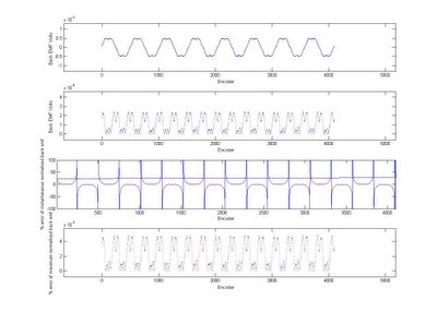
normalised back emf

Vincent has just sorted out the normalised back emf. Still seems like there is a bit of variation.


We realised that some of the variation was coming from only calculating the time over one period - when it is done over two periods it is a lot better


Here is a plot of the errors