Saturday, January 14, 2006

Setting up Labview for Back EMF measurements

I had a go at setting up LabView for Back EMF measurements. Due to Gaz's excellent VIs it was remarkably easy. I just have problems when I try to capture the HE data as well. I guess that that problem can wait until I get back as long as Vincent does not change move the encoder.

IR2175 - shape problems

At Friso's suggestion, I removed the optocoupler to check if the shape problems came from the IR2175 itself or if it came from the load on the end of the chip.

Here is the signal before I removed the opto:


and after I replaced it:


If anything, it has got worse - need to find out why

Friday, January 06, 2006

IR2175 - capturing

Today's tasks:

1. Get the plots working in code composer
2. Determine how to calculate the pulse width

Short circuit problems

WHAT A BAD START TO THE DAY...

after running the motor fine for a while it seemed to lock up after I accessed the .bit part of the watch window.

I added pulldown resistors between the phase and the top side gates as Bryon suggested to ensure that a stray voltage does not turn on the gates.


That has not solved the problem.

I have reset the CPU and emulator in the hope that it is a latch up in the DSP. I thought that reset was done each time a program was downloaded so this should not help.

As expected that did not help. I will try a power down of the DSP and then a reset..

As expected, that also did not help...

I will try one of the old programs, following that I can be sure that it is a hardware problem. I wanted to rule out all software problems first as hardware trouble shooting is difficult when the power supply is current limiting as nothing (ie gate drivers, MOSFETS) gets its correct voltage.

Tried afm_060103b.mdl with no luck - definetly have to check hardware.

The short exists with neither the motor or the interface board connected so it cannot be softwatre.

There does not seem to be a short between any of the phases and a rail which suggests that it is not a mosfet problem. To be sure, I will remove each of the gate drivers.

Still problems, removed IR2175 as well with no results.


I discovered I missed that phase C' had a short across the phase - dead MOSFETs. Not sure why but on replacement the problem is gone. Hopefully the pulldowns on the gates will stop this happening again.


now that is working, I am going to have a break from this controller and have a go at sorting out the e-bike controller

Thursday, January 05, 2006

IR2175 fun

Current problem is still to figure out how to get the 2175 working. It seems from tuesday's work that the analog side is receiving a signal. Is this being transferred correctly to the digital side?

Things are alot nicer today without the 7.5kHz whine, however at 50% duty cycle the current is a bit too high and the speed a bit too fast. I should try at 30%.

Okay that works and the speed is now 47Hz with PWM switching freq = 30kHz and duty cycle of 30%. I will try to do most of my tests with these settings.


Time to see what the PO pin is doing.


This is a really messy output. Surely this should be a nice square wave that I can trust rather that this which will rely on the opto's charateristics as to where the actual cut off is. Maybe I have a cap in the wrong place?


Better check the other phases to see if this is a typical output.


This is the PO pin for phase C. It shows similar slow transitions but does not seem to go as negative.

Looking at phase B:


it would seem from this that phase B is always saturating as the pulse width is always close to 91%. It is strange that the outputs are so different.


I had better check if it is the actual IR2175 chip so I will swap those from phases A and B.


Swapping chips does not change the output. It is clear now that A and C are similar in output and B seems to be saturating. This is strange as the resistance in each of the shunt resistors is the same (or very close). The difference possibly could be seen in the input, however for the time being, I will work with phase A to try and get it working.

Maybe it is something wrong with the sizing of the bootstrap capacitor?

Here is a plot of the bootstrap voltage V_B with reference to gnd - tomorrow I need to do further checks to see if this is the problem by measuring the V_BS voltage.


I JUST NOTICED THAT I HAD THE BRAKE MISALIGNED AND SO I AM NOW ABLE TO MOVE IT CLOSE TO THE DISK. THE SPEED IS NOW 44Hz.

I took a reading of the PO for phase A on one of the tracks that was further away from the chip and it was a lot more like that of phase B. Could my problems have to do with track layout?


Just done some more checking by measuring the pins as the signals leave the power board. I think that what I was measruing before was actually the B signal passing past the A chip. Best check the layouts more carfully next time.


Checking Resistors

R12, R13, R14, R15 are pullups and should be 10K - okay

R16, R17, R18, R19 are series resistors and should be 100R - actually 120R - okay

Just discovered that we have 2 lots of series resistors - should remove the 1k ones (R8,9,10,11)

removed these (replaced with a link) and the image looks pretty much the same. See phase A below:


Hopefully, however this will have fixed some of the problems with the signal not getting through to the intervace board.


Checking test points going into the power board connctor:

B, C and OC are fine, A is a little dodgy.

Checking inputs to optos

Same story, A was not coming through.

Problem traced back to the TP for A needed to be soldered on top as well as bottom.

Now it is time to check if I can read this waveform data in at the capture pin.

added a capture block - PWM must use timer 1 as I had to use timer 2. I hope that that does not mean that module B uses timer 2 - then I would be stuffed.

Could not get much sense out of the capture block - try again tomorrow.

Time to try a high duty cycle with the 30kHz PWM freq before I go. It looks evil, need to understand why it looks this way.

Tuesday, January 03, 2006

still trying to get the IR2175 working

Here are some things that I need to check:

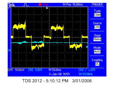
V_B - high side floating voltage should be 13- 20 V with reference to V_S

at no load it is 14.6 -good, however at load it drops to as low as 9V

check if this is at load or at low speed (done by putting 20% duty cycle on high side - 10% duty cycle on middle)

still 14.6V at 100rpm (measured by contact on tacho)

using 10% duty cycle now, and loading with the eddy current brake, I am now down to 74rpm or about 1.25 hz so I am somewhere close to operating conditions.

V_B is still at 14.5 V so I should be okay.


Now I need to understand what I am reading across the shunt resistor.


For this I have connected V_s to the ground of the oscilloscope and V+ to the signal of the oscilloscope.

this is giving me garbage with a signals that is over 5V.

THE 10K NOISE IS ANNOYING ME - TIME TO CHANGE TO 20K

this can be done by changing the "PWM_period" and the "on time" in the simlink program

still have a very annoying high pitched sound - maybe need higher than 20k. it also seems that I did not change it to 10% duty cycle before as now it is running at 30rpm (or 0.5hz).

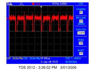
back to the voltage accross the shunt resistor.

this time I have added wires directly onto each end of the shunt resistor to be sure that I know what I am measuring.

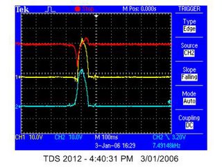
the images below show the voltage accress the shunt resistor (in red) and the reading taken current clamp (in yellow) the current clamp reading is set up for 2A.div which with a peak to peak reading of about 3 divisions, suggests a peak current of telling about 3A.


This suggests a standard peak voltage of between 40 and 60mV at 3A. For the IR2175, 260mV is meant to correspond to the peak current. This suggests that there is something wrong. I really should be getting a peak voltage of 26mV.

However if I go back to the calcs for the resistnce of the shunt resistors, I have
R_shuntA = 0.0147 (R_shuntB = 0.0145 and R_shuntC = 0.0142)

This means that the peak current will actually be 17.7A and for 3A the voltage should be 44mV which sounds a lot better.

Now my concern is that I do not understand why the reading from the shunt is in spike s when it should be reading the same current profile as the current clamp

One guess is that these spikes are from the PWM switching. It seems that they occur about every 10ms which is 100k so does not really fit in with that theory.

Better check the PWM swithing frequency.

the PWM frequency is 7.5kHz - very strange.

checked back at the model and the settings are still set for what I thought was 10k so my change to 20k was not done - strange, better figure that one out.

If i get a PWM frequecy of 7.5k for a PWM period of 10000 then the clock frequency must be 75MHz (or half the DSP clock frequency).

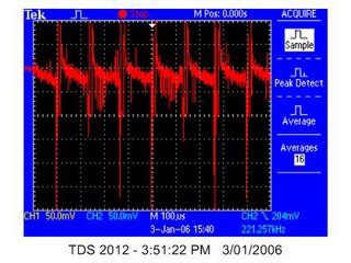
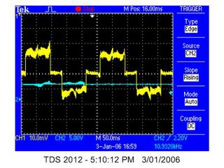
so what is creating the peaks at 100kHz in the voltage accross the shunt?

after connecting the scope up again (I have been using a differential measurement ie CH2 - CH1) I have found that I get much better results if I reference both the probes to ground - see image below:


you can clealy see here that 3 of the main wavelengths take up 400us, which corresponds to 7.5k so I have found the PWM frequency.

now if I go back to a longer timebase you can see that I have something that looks pretty similar to the current clamp reading. I assume that the additional noise shown is because of a bandwidth limit on the current clamp.


now it is time to look at the voltage that the IR2175 sees between Vs and V+

once again you can see the PWM freqency at 7.5kHz


the image at electrical frequency does not look quite as good. It seems that the negative part is not really going negative.


having a look (below) at Vs (blue), V+ (yellow) and the difference there are some strange things going on. The difference is often above 10V which is a bit strange when V+ should be reading only up to 260mV.


I just checked to see that I am measuring the correct thing and it seems that I am. Pg 3 of the datasheet says that Vin is Vin - Vs.

If I am measuring correctly then the overcurrent trip should be going off regularly - let's see.


you can clearly see that the overcurrent is regularly going off. This should be shutting down the gate driver (need to check that later as there is no obvious indication that this is happening). It seems that the overcurrent is tripping more after the current has stayed constant for a while. My guess at why this is is that when the current is rapidly changing, the impedence due to the inductance is high so less current flows. Once the current is no longer changing rapidly the imedence drops an much more current flows.

It is strange however that the overcurrent signal (which should be a digital signal) is outputting values that are in between 0 and 5V.

Time to check the overcurrent pin without the 2175 in the socket just incase this voltage is coming from elsewhere.


Though there is some noise there, it is definetly not as before, so the overcurrent pin is making a difference.

It is interesting to note that there was no significant difference in motor performance without the chip in. This suggests that the overcurrent pin is not shutting down the gate driver.


As I am stuck for the moment, I will have another go at increasing the PWM frequency. That may also shed light on other issues.


I have now fixed this up into a nice masked block.

Interesting that at7.5k the system works for 10% duty cycle but needs a couple of pushes to work at 50% duty cycle, however at 30k the system will not turn no matter how much pushing at 10% and turns fine at 50%. More investigations are due on that matter tomorrow.

Home time.