Saturday, August 19, 2006

Current control with only one phase and not motor

To get my current control working, I will initially only use the resistor bank and one phase (C as it has a current sensor in it)

I will have to do several things to set this up.

Alter the labview program so that it logs with time rather than with encoder position

DONE

Alter the simulink program to only put out on phase

DONE

Try open loop block wave output from simulink and log in labview

REALLY NEEDED TO HAVE SOME INDUCTANCE - REMOVED ROTOR AND CONNECTED ONE MOTOR PHASE

try open loop sine wave output from simulink and log in labview

DONE - TIME TO START ANOTHER BLOG JUST ON CURRENT CONTROL

attempt closed loop control using block wave (may need to use a motor phase instead of the resistor bank as there may not be enough inductance to allow proper current control)

Just blew up all the current sensors

trying to figure out why I was drawing too much current, i blew up all three current sensors. Rather than having an output of 2.5 V when at no current they were ouputting about zero.

I have removed them all and only replaced the phase C one. I will try to get some current control happening with only one phase and no motor

more high current draw on 6 wire

Having discovered why phase A was not working, I still have problems with the current draw being too high and additional problems just created with very low speed and current draw too high.

I think that I am attacking this from the wrong direction.

Much better to try something simple through one phase.

Friday, August 18, 2006

high current draw on "6 wire simple"

I had problems getting the motor to turn at all using the dsp

Some of the problem lay in that the gate drivers were buggered.

The motor now turns under "working masked open loop"

with "six wire simple" however the power supply is current limiting

I have checked in ccs and the A_effort, B_effort and C_effort are all being generated correctly for the different hall effect states.

now I should check that the gate drivers are getting appropriate signals for each hall effect state.

for HE 6

1-
2+
3-
4-
5-
6+

which translates to A open, B+ and C-

which is correct for HE6

Just out of curiosity, I checked it running on two phases and found that the motor still ran and still drew a lot of current on any combination of phases.

The motor also runs on just one phase B but still seems to draw the same amount of current.

The motor will not run on only phase A and draws no current.

The motor will run on phase C and draws a the same amount of current

If my assumptions are corrent, when the motor is running on all three phases, it will not matter if I remove phase A from the sockets - which it doesnt

there is definetly something wrong with phase A. The gate drive signals seem fine and even the voltage at the phase seems fine.

Here is an image of the differential voltage across phase A


and phase B (bit more bus voltage)


to check if it was the motor I measured the resistance across one winding and between phases. It was about 0.04R for each phase and Mohm between phases.

To further check if the problem lay in the motor, I switched the signals around in simulink and switched the bannana plugs around on the board. The problem lay with the PCB and not the motor.

Just incase there was some problem between where on the phase I had clipped on the probes, I put in some short bannana leads and clipped the probes onto them. I still got a reasonable voltage plot.


Having a look at much smaller time interval (PWM frequency), Here are the plots for phase B

4 and 6 - high


2 and 5 - open


1 and 3 - low


which is all correct for the switching table (as posted earlier)

HE table


now I will check phase A

2 and 3 - high


1 and 6 - open


4 and 5 - low


just for completeness, I had better check phase C

1 and 5 - high


3 and 4 - open


2 and 6 - low


It seems that the problem with phase A was that the connection with between the board and the banana socket was a not soldered well. Resoldering it seemed to fix the problem of A not working (however it is still drawing heaps of current)

Here is the voltage across A while only running on one phase:


Here is the voltage across B while only running on one phase:


Here is the voltage across C while only running on one phase:


while running like this, I heard a click and afterwards the speed dropped considerably and the current draw remained the same. I will have to find out what I just blew up.

problems with data logging

from the previous plot, the last P signal seems a bit strange (channel 9)

This signal looks the same as channel 13. As 13 - strain gauge is not connected, this indicates that channel 9 is not connected.

using a scope, the signal coming in from the signal conditioner looks okay.

check in MAX

turns out that i had it connected to Ai4 instead of AI3

new logging setup

I am pretty happy with how the logging is going now. With the new board, all the measuerements (piezo, current, back emf, strain gauge) come in on the same task and are logged to one file. I then have one matlab script to make all these files into one matrix.

Making all the files into one matrix makes subsequent calculations much faster as they can all be matrix operations with no loops.

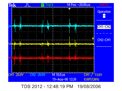
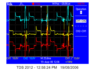
the use of the new pcb with the or gates and the one shot circuit also ensures that I get every encoder position.

Here is the m file that I use to convert all the text files into a matrix:


clear;

% set up the DAQ parameters
number_of_revolution = 11;
one_revolution = 4096;
length = number_of_revolution*one_revolution;

% read in the Encoder data
fid = fopen('Encoder.txt');
Encoder = textscan(fid, '%f');
fclose(fid);
E_gray = Encoder{1};

% Read in the time data
fid = fopen('Time_Stamp.txt');
counter = textscan(fid, '%f');
fclose(fid);
T = counter{1};

% Read in the Analog data
fid = fopen('Analog.txt');
Analog = textscan(fid, '%f %f %f %f %f %f %f %f %f %f %f');
fclose(fid);
A(:,1,1) = Analog{1};
A(:,1,2) = Analog{2};
A(:,1,3) = Analog{3};
A(:,1,4) = Analog{4};
A(:,1,5) = Analog{5};
A(:,1,6) = Analog{6};
A(:,1,7) = Analog{7};
A(:,1,8) = Analog{8};
A(:,1,9) = Analog{9};
A(:,1,10) = Analog{10};
A(:,1,11) = Analog{11};

% convert encoder to binary from gray
load g2b16_lookup.mat;
encoder_lookup_16bit = g2b16_lookup(:,2);
disp('converting encoder from gray code to binary...')
for i = 1:length
% provide status to the screen
if mod(i,one_revolution) == 0
number_of_rotations_converted = i/one_revolution
end
E(i,1) = encoder_lookup_16bit(E_gray(i)+1);
end

% create matrix for all the data one collumn for one revolution
% for each speed we have a 3 dimensions matrix (first dimension : encoder,
% second dimension : number of revolutions)and after
% Layer 1 : encoder
% Layer 2 : time
% Layer 3 : IA
% Layer 4 : IB
% Layer 5 : IC
% Layer 6 : P1
% Layer 7 : P2
% Layer 8 : P3
% Layer 9 : P4
% Layer 10 : BA
% Layer 11 : BB
% Layer 12 : BC
% Layer 13 : SG


% Find the index for E = 4095
disp('offsetting all the readings...')
j = 0;
E_start_found = 0;
while E_start_found == 0
j=j+1;
if E(j,1) == 4095;
E_start_found = 1;
end
end
offset = j;

% now I have to take offset off all the readings
E_offset(1:(length - one_revolution),1,:) = E(offset:(length - one_revolution + offset - 1),1,:);
T_offset(1:(length - one_revolution),1,:) = T(offset:(length - one_revolution + offset - 1),1,:);
A_offset(1:(length - one_revolution),1,:) = A(offset:(length - one_revolution + offset - 1),1,:);


% now I have to put the offset vectors into the matrix
disp('compiling the vectors into a matrix...')
n = 0;
for i = 1:(length - one_revolution)
if E_offset(i,1) == 4095;
n = n + 1;
end
Matrix_temp((i-(n-1)*one_revolution),n,1)=E_offset(i,1);
Matrix_temp((i-(n-1)*one_revolution),n,2)=T_offset(i,1);
Matrix_temp((i-(n-1)*one_revolution),n,3:13)=A_offset(i,1,1:11);
end

% flip the matrix so that the encoder is in increasing order
Matrix = flipdim(Matrix_temp,1);


% save the data
save('AfmMatrix.mat', 'Matrix')


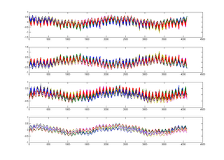
then it is easy to plot any of the measurements.

ie

clear;

% read in the raw data

load('AfmMatrix.mat', 'Matrix');
raw(:,:,:,1) = Matrix;
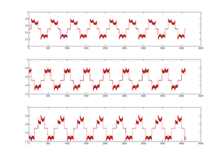

% plot I
for i = 1:3
figure(1)
subplot(3,1,i)
plot(raw(:,:,i+2,1));
end

% plot P
for i = 1:4
figure(2)
subplot(4,1,i)
plot(raw(:,:,i+5,1));
end


It is worth noting that I need to take one additional revolution when I am logging in labview so that I can start my matrix at encoder position 1.

current


piezo

Sunday, June 11, 2006

buffers that are able to provide more current

It seems that some of my problems with the current sensors are due to the innability of the 4050 or 4049s to provide adequate current to drive the leds in the optos.

Nic fourd that the 74 125 chip (as used in the ICD) could sink up to 25mA of current. As a result, I changed the 4049 that drove the optos from the IPWM signals to a 74125.

The waveform looks much nicer and now Labview has enough time to get the ADC signals as well (lack of crappy signal). This was only from a steady current source though. It may get crappy again when I am able to run the motor again.

more blown chips - how to protect them?

Effect - motor does not turn
Cause - dead gate drivers
Cause - dead voltage regulator
Cause - high voltage required for high current led to spike when the current requirement reduced.

I tried to stop this happening again by putting zeners to stop the voltage at 27v but as the fuse is 10A and each zener can only handle 176mA, I would need to have far too many zeners in parallel so that the fuse blew first.

Nic and I discussed using a DC DC converter for the power supply to the chips but we could not find any with a large enough input range for a reasonable price. We decided that it would be easier to just separate the grounds and use two separate power supplies.

Wednesday, June 07, 2006

finishing off ringing for the moment

I realised that I should have been meausing the high side between phase and gate drive signal rather than ground. this is for 33R


you can see here that there are none of the really high spikes but still a fair amount of ringing. I will just have a quick go at 120R to see if this gets a bit better.


that is no better - have a look at the low side

Tuesday, June 06, 2006

what size resistor to stop the ringing

as can be seen from the previous post, there is a lot of ringing with the 3r3 resistors

there is no ringing with the 1k resisistors - need somewhere in between

try 82R in series with 1k = about 75R

there is still a fair amount of ringing


one app note suggested that I should have the gate drive resistor as close as possible to the gate. I have moved an 82R as close to the gate for the following results


I tried adding a 16V zener between phase and the high gate drive but things went pear shaped.

instead, I tried to use a 330R for the gate drives


which looks pretty terrible

ty 33r close to gate

what is the minimum deadband that I can have with 3r3 resistors?

pulse width 50%
deadband prescaler from 31 to 1
deadband period left at 15

this setup does not draw too much current (indicating that the deadband is adequate)


put on the 3r3s on A' B' and C' and check the shapes for six wire simple

does not draw too much current which is a good start

still on HE = 1

here is the image for A and B


and for C


motor does not turn - increase the voltage factor from 350 to 700

also probably did not turn as I did not have the hall effects plugged in

turns now but is drawing heaps of current - better get a bit more deadband

changed both deadband prescalers to 4

still drawing too much current - here is the crossover point


try a prescaler of 8 and then it is time to attempt to get rid of the ringing

here is the ringing in the deadband zone with the

photos do not seem to be working at the moment see folder 060606

for deadband prescaler = 8

checking six wire open loop program with 3R3 gate resistors

HE = 1
A = 0
B = -1
C = 1

as expected, A and B have the low gate on all the time (barring the dead band) - see below


A little more interesting is phase C which is meant to be high but is only on for maybe 20% of the time (due to the huge amount of deadband)


I have left the 1k resistors on A' B' and C' and the interesting comparison is of B' which should be high. As you can see from the image below, it is proably high for a lot longer than the previous image.


the obvious thing at this stage would be to see how much deadband I can get away with on A, B and C with the 3r3 resistors

Gate drive resistors

from measurements, it has become clear that the gate drive resistors are too large.

here is the gate drive signal before the resistor


here is the gate drive signal after the 1K gate drive resistor


I decided that after seeing several reference designs (see binder with "gate drive app notes" that I should try a 3r3 resistor

here is the gate drive signal after the 3.3R resistor


I will go with that for each of the resistors. The only problem for having a lower resitsor value is apparently if there is too much ringing. I cannot see that.

these shapes are great, unfortunately the motor does not turn when these gate drive resistors are used. The motor seems to prefer it when the gate drive signal is a crappy shape.

Sunday, June 04, 2006

XTIMING0

201343 actually works - try to remove active bit

110001000001111111

200831

works - try on 6

definitely does not work

110001001001111111

201343

i have had real trouble getting these timing registers to update.

I have tried to restart everythign but that does not help. I am just getting the default values of these registers

more external memory timing

I determined yesterday that the timing selections did not work if I assumed that Xready was not used.

That was at the minimum timing settings for xready but I will assume for the moment that it must use xready as that works.

I still cannot get access to the datasheets for the external memory chips to see if they use xready.

I now have access to the data sheet for the IS61LV6416-105 and I think that there is no connection to xready. This would be an output from the external memory chip and the only control signals are inputs.

The fastest access time that can be expected is 8ns.

The easiest way to configure this would be to assume that xready is not used and increase the timings until it works. Go to a maximum timing but with xready disabled to see if there is any chance that this will work.

below is the default changed to have xready = 0.

0000 0000 0100 0011 0011 1111 1111 1111

or

00000000010000110011111111111111

or

4407295

(31-24) 0000 0000 - reserved
(23) 0 - reserved
(22) 1 - X2TIMING
(21-18) 00 00 - reserved
(17-16) 11 - XSIZE
(15) 0 - READYMODE
(14) 0 - USEREADY
(13-12) 11 - XRDLEAD
(11-9) 111 - XRDACTIVE
(8) 1 - XRDTRIAL
(7) 1- XRDTRIAL
(6-5) 11 - XWRLEAD
(4-2) 111 - XWRACTIVE
(1-0) 11- XWRTRIAL

XintfRegs.XTIMING6.all = 4407295;

runs okay

try to remove all the write parts to simplify (last 7 bits)

00000000010000110011111110000000

or

4407168

works (as expected)

try changing down to xtiming2 = 0

00000000000000110011111110000000

212864

works

lets summarise

(31-24) 0000 0000 - reserved
(23) 0 - reserved
(22) 0 - X2TIMING
(21-18) 00 00 - reserved
(17-16) 11 - XSIZE
(15) 0 - READYMODE
(14) 0 - USEREADY
(13-12) 11 - XRDLEAD
(11-9) 111 - XRDACTIVE
(8-7) 11 - XRDTRIAL
(6-5) 00 - XWRLEAD
(4-2) 000 - XWRACTIVE
(1-0) 00- XWRTRIAL


try reducing XRDLEAD XRDACTIVE and XRDTRIAL to 1 each

00000000000000110001001010000000

or

201344

works

I know that lead must be 1 - lets see if either active or trail can be 0

try trail

00000000000000110001001000000000

works

try active

00000000000000110001000000000000

200704

does not work!!

00000000000000110001001000000000
201216

must be the answer

but...

Trouble Writing Target CPU memory: Error 0x00000002/-1153 Error during: Memory, The memory at 0x00100002 continually indicated it was 'not ready' All memory operations currently in progress were aborted in order to regain control of the processor. This is considered a catastrophic event, but the debugger should still be able to access memory and CPU registers. System state has been altered. It is strongly advised that the processor should be reset before resuming execution,


maybe I should set up the write states again

00000000000000110001001001111111

201343

works fine

now try to do the same to zone 0 (encoder)

201343


does not work

start another post on this topic later - home time

Saturday, June 03, 2006

extermal memory timing

try chris' external memory timing

XintfRegs.XTIMING6.all = 202281;

motor does not turn

change back

from the data sheet, here is an example of valid timings when not sampling XREADY

0000 0000 0100 0011 1001 0000 0010 0000
or
00000000010000111001000000100000
or
4427808

(31-24) 0000 0000 - reserved
(23) 0 - reserved
(22) 1 - X2TIMING
(21-18) 00 00 - reserved
(17-16) 11 - XSIZE
(15) 1 - READYMODE
(14) 0 - USEREADY
(13-12) 01 - XRDLEAD
(11-9) 000 - XRDACTIVE
(8) 0 - XRDTRIAL
(7) 0- XRDTRIAL
(6-5) 01 - XWRLEAD
(4-2) 000 - XWRACTIVE
(1-0) 00- XWRTRIAL

motor makes a lot of ugly noise but does not run

I must need to use XREADY

I cannot find the data sheet for the external memory that I need to determine the wait states as the internet is playing up.

I will work on the current sensor problems instead.

block wave lookup for encoder

I have done this two ways, one with equal spacing for all the states and one directly from the logged data (ie which hall state corresponds to each encoder reading)

After a lot of stuff ups, i have two plots that closely resemble each other and sort of work. I think that they are not working completly properly because of the access times to external memory.

I think that I will use the equal spacing one as then I know what the block wave is.

Here are the relationships from the two:

Equal spacing


Experimental


I ref