Saturday, August 19, 2006

Current control with only one phase and not motor

To get my current control working, I will initially only use the resistor bank and one phase (C as it has a current sensor in it)

I will have to do several things to set this up.

Alter the labview program so that it logs with time rather than with encoder position

DONE

Alter the simulink program to only put out on phase

DONE

Try open loop block wave output from simulink and log in labview

REALLY NEEDED TO HAVE SOME INDUCTANCE - REMOVED ROTOR AND CONNECTED ONE MOTOR PHASE

try open loop sine wave output from simulink and log in labview

DONE - TIME TO START ANOTHER BLOG JUST ON CURRENT CONTROL

attempt closed loop control using block wave (may need to use a motor phase instead of the resistor bank as there may not be enough inductance to allow proper current control)

Just blew up all the current sensors

trying to figure out why I was drawing too much current, i blew up all three current sensors. Rather than having an output of 2.5 V when at no current they were ouputting about zero.

I have removed them all and only replaced the phase C one. I will try to get some current control happening with only one phase and no motor

more high current draw on 6 wire

Having discovered why phase A was not working, I still have problems with the current draw being too high and additional problems just created with very low speed and current draw too high.

I think that I am attacking this from the wrong direction.

Much better to try something simple through one phase.

Friday, August 18, 2006

high current draw on "6 wire simple"

I had problems getting the motor to turn at all using the dsp

Some of the problem lay in that the gate drivers were buggered.

The motor now turns under "working masked open loop"

with "six wire simple" however the power supply is current limiting

I have checked in ccs and the A_effort, B_effort and C_effort are all being generated correctly for the different hall effect states.

now I should check that the gate drivers are getting appropriate signals for each hall effect state.

for HE 6

1-
2+
3-
4-
5-
6+

which translates to A open, B+ and C-

which is correct for HE6

Just out of curiosity, I checked it running on two phases and found that the motor still ran and still drew a lot of current on any combination of phases.

The motor also runs on just one phase B but still seems to draw the same amount of current.

The motor will not run on only phase A and draws no current.

The motor will run on phase C and draws a the same amount of current

If my assumptions are corrent, when the motor is running on all three phases, it will not matter if I remove phase A from the sockets - which it doesnt

there is definetly something wrong with phase A. The gate drive signals seem fine and even the voltage at the phase seems fine.

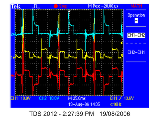
Here is an image of the differential voltage across phase A


and phase B (bit more bus voltage)


to check if it was the motor I measured the resistance across one winding and between phases. It was about 0.04R for each phase and Mohm between phases.

To further check if the problem lay in the motor, I switched the signals around in simulink and switched the bannana plugs around on the board. The problem lay with the PCB and not the motor.

Just incase there was some problem between where on the phase I had clipped on the probes, I put in some short bannana leads and clipped the probes onto them. I still got a reasonable voltage plot.


Having a look at much smaller time interval (PWM frequency), Here are the plots for phase B

4 and 6 - high


2 and 5 - open


1 and 3 - low


which is all correct for the switching table (as posted earlier)

HE table


now I will check phase A

2 and 3 - high


1 and 6 - open


4 and 5 - low


just for completeness, I had better check phase C

1 and 5 - high


3 and 4 - open


2 and 6 - low


It seems that the problem with phase A was that the connection with between the board and the banana socket was a not soldered well. Resoldering it seemed to fix the problem of A not working (however it is still drawing heaps of current)

Here is the voltage across A while only running on one phase:


Here is the voltage across B while only running on one phase:


Here is the voltage across C while only running on one phase:


while running like this, I heard a click and afterwards the speed dropped considerably and the current draw remained the same. I will have to find out what I just blew up.

problems with data logging

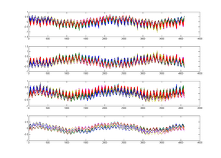
from the previous plot, the last P signal seems a bit strange (channel 9)

This signal looks the same as channel 13. As 13 - strain gauge is not connected, this indicates that channel 9 is not connected.

using a scope, the signal coming in from the signal conditioner looks okay.

check in MAX

turns out that i had it connected to Ai4 instead of AI3

new logging setup

I am pretty happy with how the logging is going now. With the new board, all the measuerements (piezo, current, back emf, strain gauge) come in on the same task and are logged to one file. I then have one matlab script to make all these files into one matrix.

Making all the files into one matrix makes subsequent calculations much faster as they can all be matrix operations with no loops.

the use of the new pcb with the or gates and the one shot circuit also ensures that I get every encoder position.

Here is the m file that I use to convert all the text files into a matrix:


clear;

% set up the DAQ parameters
number_of_revolution = 11;
one_revolution = 4096;
length = number_of_revolution*one_revolution;

% read in the Encoder data
fid = fopen('Encoder.txt');
Encoder = textscan(fid, '%f');
fclose(fid);
E_gray = Encoder{1};

% Read in the time data
fid = fopen('Time_Stamp.txt');
counter = textscan(fid, '%f');
fclose(fid);
T = counter{1};

% Read in the Analog data
fid = fopen('Analog.txt');
Analog = textscan(fid, '%f %f %f %f %f %f %f %f %f %f %f');
fclose(fid);
A(:,1,1) = Analog{1};
A(:,1,2) = Analog{2};
A(:,1,3) = Analog{3};
A(:,1,4) = Analog{4};
A(:,1,5) = Analog{5};
A(:,1,6) = Analog{6};
A(:,1,7) = Analog{7};
A(:,1,8) = Analog{8};
A(:,1,9) = Analog{9};
A(:,1,10) = Analog{10};
A(:,1,11) = Analog{11};

% convert encoder to binary from gray
load g2b16_lookup.mat;
encoder_lookup_16bit = g2b16_lookup(:,2);
disp('converting encoder from gray code to binary...')
for i = 1:length
% provide status to the screen
if mod(i,one_revolution) == 0
number_of_rotations_converted = i/one_revolution
end
E(i,1) = encoder_lookup_16bit(E_gray(i)+1);
end

% create matrix for all the data one collumn for one revolution
% for each speed we have a 3 dimensions matrix (first dimension : encoder,
% second dimension : number of revolutions)and after
% Layer 1 : encoder
% Layer 2 : time
% Layer 3 : IA
% Layer 4 : IB
% Layer 5 : IC
% Layer 6 : P1
% Layer 7 : P2
% Layer 8 : P3
% Layer 9 : P4
% Layer 10 : BA
% Layer 11 : BB
% Layer 12 : BC
% Layer 13 : SG


% Find the index for E = 4095
disp('offsetting all the readings...')
j = 0;
E_start_found = 0;
while E_start_found == 0
j=j+1;
if E(j,1) == 4095;
E_start_found = 1;
end
end
offset = j;

% now I have to take offset off all the readings
E_offset(1:(length - one_revolution),1,:) = E(offset:(length - one_revolution + offset - 1),1,:);
T_offset(1:(length - one_revolution),1,:) = T(offset:(length - one_revolution + offset - 1),1,:);
A_offset(1:(length - one_revolution),1,:) = A(offset:(length - one_revolution + offset - 1),1,:);


% now I have to put the offset vectors into the matrix
disp('compiling the vectors into a matrix...')
n = 0;
for i = 1:(length - one_revolution)
if E_offset(i,1) == 4095;
n = n + 1;
end
Matrix_temp((i-(n-1)*one_revolution),n,1)=E_offset(i,1);
Matrix_temp((i-(n-1)*one_revolution),n,2)=T_offset(i,1);
Matrix_temp((i-(n-1)*one_revolution),n,3:13)=A_offset(i,1,1:11);
end

% flip the matrix so that the encoder is in increasing order
Matrix = flipdim(Matrix_temp,1);


% save the data
save('AfmMatrix.mat', 'Matrix')


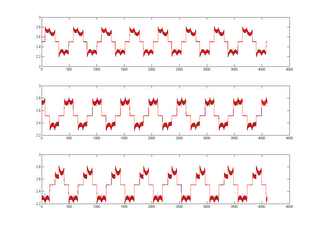
then it is easy to plot any of the measurements.

ie

clear;

% read in the raw data

load('AfmMatrix.mat', 'Matrix');
raw(:,:,:,1) = Matrix;


% plot I
for i = 1:3
figure(1)
subplot(3,1,i)
plot(raw(:,:,i+2,1));
end

% plot P
for i = 1:4
figure(2)
subplot(4,1,i)
plot(raw(:,:,i+5,1));
end


It is worth noting that I need to take one additional revolution when I am logging in labview so that I can start my matrix at encoder position 1.

current


piezo