Thursday, February 23, 2006

Back emf testing

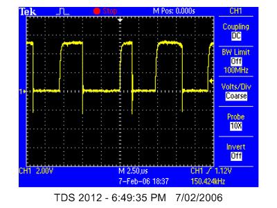
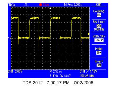
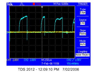
Vincent has done some good testing of back emf. This is meant to be all at the same speed:

overall


best peak zoomed


worst peak zoomed

Monday, February 20, 2006

c code to use XINT1

I have modified one of Jess' old programs to attempt to use XINT1. The main program only loops and then the ISR also loops.

At the moment, the isr is not being accessed. See below for the diagram from the system control and interrupts guide p 6-2 that shows what needs to be set up.


I have setup the PIEIER:

// set up XINT1
EALLOW; // This is needed to write to EALLOW protected register
PieVectTable.XINT1 = &xint1_isr; //define where xint1_isr is in the vector table
PieCtrlRegs.PIEIER1.bit.INTx4=1; // PIE Group 1, INT4 (XINT1) sci rev guide p 6/23
EDIS;


however I have not set up INTM or IER which could be why it is not working

another good diagram is:


this should tell me how far through the interrupt is getting. I should be able to see if PIEACKx = 1 when I set off the interrupt.

Saturday, February 18, 2006

Using XINT1

To get one current sensor to work, I will start by using XINT1.

First task is to understand interrupt control - see figure in previous post.

XINT1CR looks like a register.

Here is something useful from google:

If i enable the external interrupt, the interrupt-flag in the
XINT1CR - Register is set but the pogramm doesn´t jump to my defined
subroutine.

I set the XINT1CR = 0x8003;

//0x0001 enable
//0x0002 low priority ( vector address 0Ch ) int6
//0x0004 polarity ( interrupt on falling edge )
//0x8000 clear int flag by writing a 1


I found some useful stuff in Jess's files (MotorcontrolSCI.c) but I do not think that she used this in the final program. I think that she was going to use this for the ADC callibration routine.

EnableInterrupts();

// XIntruptRegs.XINT1CR.all = 0x0005; //allow External interrupt XINT1
// interrupt generated by low-high transition

Interrupts in C

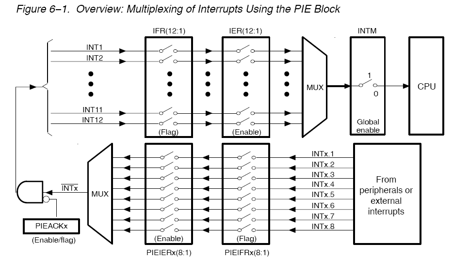
It has come clear from my attempts to understand the interrupt block, that I will need to first write a program that uses interrupts in C-code in CCS.

Best check what Jess did.

I cannot find if Jess used any interrupts.

I am fed up with TI/ spectrum digitial etc documetnation. I cannot find anywhere what the appropriate pins are for external interrupts. There are meant to be 96 possible connections for interrupts, and I understand that some of those will be internal, however I would have hoped that there are more than 3 external interrupts available. The ones that I can find on the spectrum digtal schematic are:

XINT1n_XBIOn [P8 pin 5 and 22]
XINT2n_ADCSOC [P4 pin 2]
XNMIn_XINT3 (or should it be XINT13) [P2 pin 46]

The ones that I can find in the TI documentation (System control and interrupts referece guide) are:

XINT1_/XBIO [GPIOE0]
XINT2_ADCSOC [GPIOE1]
XNMI_XINT13 [GPIOE2]

As all the info that I can find suggests that the unmasked interrupts are 1,2 and 13, I think that the schematics should have 13 instead of 3.

Here is the diagram from chapter 6 of system control and interrupt souces:


I guess that I am probably limited to using only these pins for interrupts. I hope that I can use them all as I will need one for each of the three current sensors. I thought that I read somewhere that 13 was reserved for the DSP.

In simulink, GPIOE0,1 and 2 are able to be used as GPIO so they may all be available.

Friday, February 17, 2006

modification of interrupt block

I think that the best way will be to modify an exsisting interrupt block...


Creating a Customized Asynchronous Library


This section describes how to implement asynchronous blocks for use with your target RTOS, using the Async Interrupt and Task Synchronization blocks as a starting point. (Rate Transition blocks are target-independent, so you do not need to develop customized rate transition blocks.)

You can customize the asynchronous library blocks by modifying the block implementation. These files are

The block's underlying S-function MEX-file

The TLC files that control code generation of the block

In addition, you need to modify the block masks to remove VxWorks-specific references and to incorporate parameters required by your target RTOS.

Custom block implementation is an advanced topic, requiring familiarity with the Simulink MEX S-function format and API, and with the Target Language Compiler (TLC). These topics are covered in the following documents:

The Overview of S-Functions in the Simulink S-Functions documentation describes MEX S-functions and the S-function API in general.

The Target Language Compiler documentation and Writing S-Functions for Real-Time Workshop describe how to create a TLC block implementation for use in code generation.

The sections below discuss the C/C++ and TLC implementations of the asynchronous library blocks, including required SimStruct macros and functions in the TLC asynchronous support library (asynclib.tlc)

MEX S-Function Wrapper

maybe I would be better off using MEX S-Function Wrapper

Creating S-functions using an S-function wrapper allows you to insert C/C++ code algorithms in Simulink and Real-Time Workshop with little or no change to your original C/C++ function.

that way I can write the function in C and get it working before making it into a block.

Writing Noninlined S-Functions

type mexext in the command window

mexw32 is the result.


Noninlined S-Function Parameter Type Limitations

Parameters to S-functions can be of the following types only:

Double precision

Characters in scalars, vectors, or 2-D matrices

For more flexibility in the type of parameters you can supply to S-functions or the operations in the S-function, inline your S-function and consider using an mdlRTW S-function routine.

Thursday, February 16, 2006

determining pulse width

Just had a read of the document about implementing IR2175 interface with a TI dsp. This is the plan:

1. connect the current sensor to both an external interrupt pin and the capture pin.

2. configure an interrupt routine related to that interrupt pin to read both values from the capture stack and do the pulse width calculations.

To do this, i need to learn how to implement interrupt routines and possibly write user defined functions.

here are some possible useful quotes from the help files:

Scheduling and Timing

A timer interrupt is used to run generated code in real time on the C2000 DSP. Each iteration of the model solver is run after an interrupt has been posted and serviced by an interrupt service routine (ISR). The code generated for the C28x uses CPU_timer0. The code generated for the C24x uses an Event Manager (EV) timer, which you can select.


intro text

Executing code generated from Real-Time Workshop on a particular target requires that Real-Time Workshop generate target code that is tailored to the specific hardware target. Target-specific code includes I/O device drivers and interrupt service routines (ISRs). Generated source code must be compiled and linked using CCS so that it can be loaded and executed on a TI DSP. To help you to build an executable, the Embedded Target for TI C2000 DSP uses the Link for Code Composer Studio to start the code building process within CCS. Once you download your executable to your target and run it, the code runs wholly on the target. You can access the running process only from the CCS debugging tools or across a link using Link for Code Composer Studio Development Tools.

Each of the existing blocks have ISR routines in them. The capture block uses an interrrupt based on the sample time to output the values in the stack. I need to make a block that outputs the values in the stack when an external interrupt goes off.

Types of S-Functions

to start with, it seems that the easiest type of s-function to use is a Noninlined S-Functions. This may not be the most efficient code, however it is an obvious place to start.

making use of the semiperiod info

first I need to understand the meaning of C28xCAP_o2. Which I think that I do after reading the following:


The status flag outputs are

0 -- The FIFO is empty. Either no captures have occurred or the previously stored capture(s) have been read from the stack. (The binary version of this flag is 00.)

1 -- The FIFO has one entry in the top register of the stack. (The binary version of this flag is 01.)

2 -- The FIFO has two entries in the stack registers. (The binary version of this flag is 10.)

3 -- The FIFO has two entries in the stack registers and one or more captured values have been lost. This occurs because another capture occurred before the FIFO stack was read. The new value is placed in the bottom register. The bottom register value is pushed to the top of the stack and the top value is pushed out of the stack. (The binary version of this flag is 11.)


The timing of my sample time will be critical.

I think that I will be unable to use a standard block to calculate the current from the PWM output. Time to look at how I can write a user defined block.

another day of trying to sort out captures in simulink

Using this model:


just looked at the stack:

11097
11569

the difference is:
-472

which is somwhere arount the 500 that I expected.

the variable saved to memory from the output of the CAP block is always about 18000. I have no idea what this is.

This is what the help describes as happening:


Send data format

The type of data to output:

Send 2 elements (FIFO Buffer) -- Sends the latest two values. The output is updated when there are two elements in the FIFO, which is indicated by bit 13 or 11 or 9 being sent (CAP x FIFO).

Why 13 or 11 or 9?


If the CAP is polled when fewer than two elements are captures, old values are repeated. The CAP registers are read as follows: The CAP x FIFO status bits are read and the value is stored in the status flag.


The top value of the FIFO is read and stored in the output at index 0. The new top value of the FIFO (the previously stored bottom stack value) is read and stored in the output at index 1.


I had a thought that I may be loosing data due to the data format, however as it is set to "auto" it should not be loosing any data.

maybe not:

The auto option uses the datatype of a connected block that outputs data to this block. If this block does not receive any input, auto sets the dataype to double.

if I set the output data type to something larger than double...

tried uint32 and now it is changing but stillseems to bear no resemblance to the values in the stack.


Using the quick watch window (&I_pwm_testing_B.C28xCAP_o1[0]), I determined at which address the stack variables are stored in and added a "from memory" block to see their contents.


for some reason the contents of the saved memory locations are not the same as the contents of the stack - maybe I should not have uint32

now:

stack0(saved in memory) = 32512
stack1(saved in memory) = 21760

period(saved in memory) = 10752

which is correct subtraction, however:

I_pwm_testing_B.C28xCAP_o1[0] = 49331.0
I_pwm_testing_B.C28xCAP_o1[1] = 49801.0

which is nothing like what is saved in the memory.

Maybe it is something to do with the sample time and the memory only being saved once every sample time.

to test that theory, I have used memtest0 and memtest1 that are "from memory" at the same location. in theory, they should always have the same value in them...

and they do.

SAMPLE_TIME is now set to 0.0001sec. (10K)

on a rebuild the addresses for I_pwm_testing_B.C28xCAP_o1[0] and
I_pwm_testing_B.C28xCAP_o1[1] have changed. This is not a long term solution.


time to see how quick this baby can go.


Try sample time 0.00001 (100K)

Seems to work but has not helped my memory problems

Try sample time 0.000001 (1M)

Still seems to work but has still not helped the memory problems

I had better check if I can actually have too fast a sample time - otherwise I may not be increaing the sample time at all.

Try sample time 0.00000001 (100M)

Still has not crashed, however now all registers and memory locations except EvaRegs.CAP1FIFO are zero.

I had better go back to a realistic sample time and try to undersand what the outputs of the CAP block are doing. Maybe try 100K.

I now have C28xCAP_o2 changing between 1.0 and 3.0 which I need to understand. I noticed that some of the values I am looking at are double and some are uint16. As double seems to be the default for most of the cap values, i have changed all the memory locations to double for consistency.


THAT WAS MY PROBLEM. NOW THEY ALL AGREE.


The period now always seems to be -471.

I will try now to look at the period between any edge. This should either give me the high semiperiod or the low semiperiod.

I now have -210 or -261. If I change the current flow, I should get a much different ratio.

With the current setup to just before the /OC trips, the semiperiods are: -52 and -425.

this equates to: 10.9%

now to put my mind at ease, I will have a look at the semiperiod if I short out the V+ and the Vs pins of the IR2175. That should give me a 50% ontime.

226 and 245 = 48%

I guess that that is the fault of the poor shape of the square wave.

Wednesday, February 15, 2006

Frequency spectrum with dyno fully assembled

I couldn't help myself. I could not wait until tomorrow to find out what the frequency spectrum for the whole motor assembly was. Maybe I should have waited and not ruined my night.

manipulation of the CAP signal

This data is now stored in a buffer. I have to learn to deal with a buffer - maybe using memory blocks.

I_pwm hardware checking

One obvious reason that I am getting zero into the registers of the CAP block is that I_pwm 1 is not connected to CAP1.

Checked the schematics and it should be connected.

Should check using oscillicsope to see if is is getting to the correct pin on the DSP.

as usual, I have stuffed up the variboard and connected the wrong track - hope this works

Now the signal is coming into and out of the opto. I had better remember that the signal is inverted in the opto.

EXCELLENT - I HAVE VALUES IN THE .CAP VARIABLES

time to work out how to take these varables away from eachother.

Low frequency problems

Ben has found that when impacting the housing from the ends, he is getting a low frequency vibration of about 25Hz on sensors 3 and 4. This is happening regardless of which end is impacted.

results for impact from sensor 3 and 4 end (motor end of base)


results for impact from sensor 1 and 2 end (brake end of base)


for all these ffts we have decided to use the "short" version of the time domain signals (only cropped to the left) rather than the "shorter" version of the time domain signal (cropped left and right). Using N=8192 for the fft effectively crops the right hand side.


Possible problems


Firstly we checked that all the sensor bolts were tight (they were).

Next, to detemine if it was a sensor/ housing issue or a base issue, we bolted the housing and sensors on to the housing rotated by 180 degrees.

Below are the power spectrums for an impact near 3 and 4 (brake end of base)


impact near sensors 1 and 2 (motor end of base)

I_pwm capture into DSP

Now that I have a known signal from my IR2175, I should try some capture into the DSP. There is an application note for this that I should have a look at first. It may also be time to figure out how to output data somehow.

Set up a Capture input and send the output of the capture block to a memory location. Program compiles but there is only zero at the memory location.

LUNCH TIME

I thought that I should check that I have adequte resolution with a pulse frequency of 150KHz (6.7us).

Assuming that I use no multiplier, at 75MHz (0.01334us) I should have 75000/150 = 500 possible states.

If I take away 18% that is not variable then I have 205 states in each of the positive and negative directions. I hope that is enough!!.

Ben's vibration testing on just housing and shaft

Ben has been doing some pretty good work on the vibration response to hammer excitation. Here are some images:

Original time domain signals


Cropped time domain signals


Power spectrum for each sensor


As we are only interested in torque, Ben tried to get a "torque" signal by: (S1+S3-S2-S4)/4.

Average cropped time domain signal


Average power spectrum

Tuesday, February 14, 2006

Tuesday's DC current sensing

The problem yesterday was a dead IR2175. Today it looks a little better!


Now the OC has sorted itself out, however I still have a large pulse width for no current.

For some reason, there is a large voltage (approx 0.4V) between V+ and Vs. If I short these pins I should get 50% duty cycle.


Finally - something is working properly.

Now I need to work out why I am getting such a large voltage across V+ and Vs.

I discoverd I forgot a link on the PCB - it is pretty much working now with the pulse width doing what it should in both current directions. The only problem is that there is still a small offset when the current is meant to be zero - see below.


It is also interesting that even with this circuit, there is a bit of a slope when going up to 5V. Maybe I can try experimenting with smaller pullups.

Monday, February 13, 2006

DC current sensing continued

Now that the DC current sensing board has been finished - here are a few of the specs:

Vcc - 12V (15 on actual board)
Vbs - 12V (15 on actual board)

Here is the schematic and the PCB layout for variboard.


Initial problems occured when I did not reference Vin or Vout to GND. Once I fixed that up the results were a little better.


there are still a few problems:

1. the most obvious: why are all the signals going negative?
2. there is no current flowing through this setup, why is the square wave not 50%?
3. Why is the /OC pin going low if there is no current flowing?

Maybe I should connect both Vin and Vout to GND to make sure that no current is being sensed.


This scope plot is amost identical. Why? Why? Why?

Intersting to note that the of time is: 73.15ns and the off time: 6.749us

therfore the % on time is (73.15 * 10-3)/(73.15 * 10-3 + 6.749) = 1.1%. Something must be wrong with the measure function as I can see that that is not the case.


Okay... the negative problem was because I had the ground lead for the scope connected to the wrong track - see below. Still have other problems.


As I still have other problems, I thought that the problem may be the chip, however I get the same result if I change the chip.

My main problem is that there is no change in pulse width for a change in voltage across the V+ and Vs.

I am a tool. The "R" resistor that is meant to be 10 - 20R, I have used a 1K and it is open circuit anyway. Better change that to a 10R

Still a crap signal - home time now.

Thursday, February 09, 2006

DC current sensing!

Following a discussion with Friso, we decided that it would be best to make a circuit that used the IR2175 in a DC situation. This will allow me to callibrate the sensors by supplying a fixed current from a digital power supply.

The problem with this approach is that I will need a separate power supply to achive Vbs as there will be no switching to charge up the bootstrap circuit.

CALCULATIONS

Shunt resistor

I only want to use a current of 2A

V = IR = 0.260

therfore

R = 0.260/2

= 0.13

or 7 x 1 ohm in series.

and for the power:

P = IV

V = IR

I = V/R

therfore

P = V^2/R

= 0.26*0.26*1
= 0.0676

so quarter watt will be fine.


Motor simulation resistors

These resistors need to drop 12V using 2A

V = IR

R = V/I
= 6 ohms


total power

P = IV
= 2*12
= 24 W

I need 3 10W 19R in series

Tuesday, February 07, 2006

checking the PO pin

I should check that the PO pin is connected correctly. In figure 8 in the application note there is only a pullup shown. I have taken the series resistor out and the result seems a little better.


The other thing to do is to check if it helps to have the pull up closer to the chip. I will check this now.

first removed what I thought was the pullup (R12) the result is shown below which seems very similar to the previous.


to be sure that I have disconnected all the resistors, I have removed a link close to the chip. This time I get the change that I was after.


Now I will try with just a 1.2K pullup directly from PO to 5V.


That is much nicer. Better try now with a load on this. I will try to go back to the original circuit but with a 1k pullup.

I decided it was easier to just add a series resistor (82R). The result looks worse. but remember that it is driving the optocoupler.


I will just remove this an put in a wire as the app note suggests. I will also replace the 1k2 with 1k pullup (minimum app note recommends)


looks okay. Tomorrow I will need to determin how small I can make the pullup to improve the shape.

I just had a thought that the app note recommends the use of 1k to 10k pullups, however that is for interfaceing directly into a microcontroller or dsp. Maybe as I am going into an opto first, I need more current.

checking the bootrap circuit

After that interesting little interlude, it is time to keep checking the current sensing circuit. I now think that the negative transient protection is working fine (at least for the current operating conditions). It it time to check the bootstrap circuit.

As listed in an earlier post, I am unsure of how I chose the bootstrap components. I had better convince myself that these are appropriate.

here is the plot for Vs (blue) Vb (yellow) and Vbs (red).


I think that it shows that Vbs is a constant 15V which I think is good.

variation of motor voltage in different HE positions

an interesting outcome of checking the Vs pin on the IR2175 for negative transients is that for differnet hall effect postions, the voltage shape for each PWM pulse is different.

When the motor is moving in a clockwise direction, in hall effect positions (afm_060105_B.HE in watch window) 4 and 5 the shape is:


I just blew up a FET trying to stop the motor to check. better try with the switches.

1 and 6 the shape is:


for 3 and 2 the shape is:


remembering that the order of the hall effects is:

451326

checking the negative transient protection

time to go through and check each of the circuits.

Negative transient protection should not be too difficult to check. I will just have a look at the Vs pin with reference to the COM pin.

the scope shows that there are no negative transients.

current sensing - back to the schematics

Time to go back to the schematics.

I have previously checked that I have correct values for all the components. I will check again and document what values are correct and where I got the info for their values from.

Looking at figure 1 in the application note:


I need to choose: R, R_sense, C_bs, D_bs and the diode from V_s to COM (D_vs).


R_sense calculations are shown earlier in this blog.


R and D_vs are present to eliminate any negative transients from the Vs pin. (see app note p4)


R should be 10 - 20 ohm (see app note p4)

D_vs should be a 1A diode that has a recovery time of less than 100ns.

WHAT DIODE DID I CHOOSE?


C_bs and D_bs are needed for the bootstrap circuit.

HOW DID I CHOOSE THE SIZE OF THESE COMPONETS?


I also need a 1 - 10K pullup on the PO (app not p1).


done with 10K


I also need to choose and determine the location for a filter cap(0.1uF).


here i have found a problem. The filter cap (decoupling cap) has beed added between Vcc and Vs rather than Vcc and COM.

I have moved the filter cap to the correct place and connected them both directly to the pins of the chip to ensure that they are as close as possible as the app note recommends.


not much seems to have been fixed.

back to current sensing problems

This is the week to sort out the current sensing problems.

This is the signal that I am getting from the IR2175 at the moment:

Settings are: 30kHz switching, and 30% duty cycle. Speed is 55Hz.


just as a check, detemine the frequency:

period approx 2.5 * 2.5 * 10^-6 sec

therfore frequcncy = 1/ (2.5 * 2.5 * 10^-6) sec

= 160 kHz

so I am measuring the correct signal.

Now I had better check with the opto out again - just to be sure that it is the chip and not the load.


as before, this gives no real improvement.